–
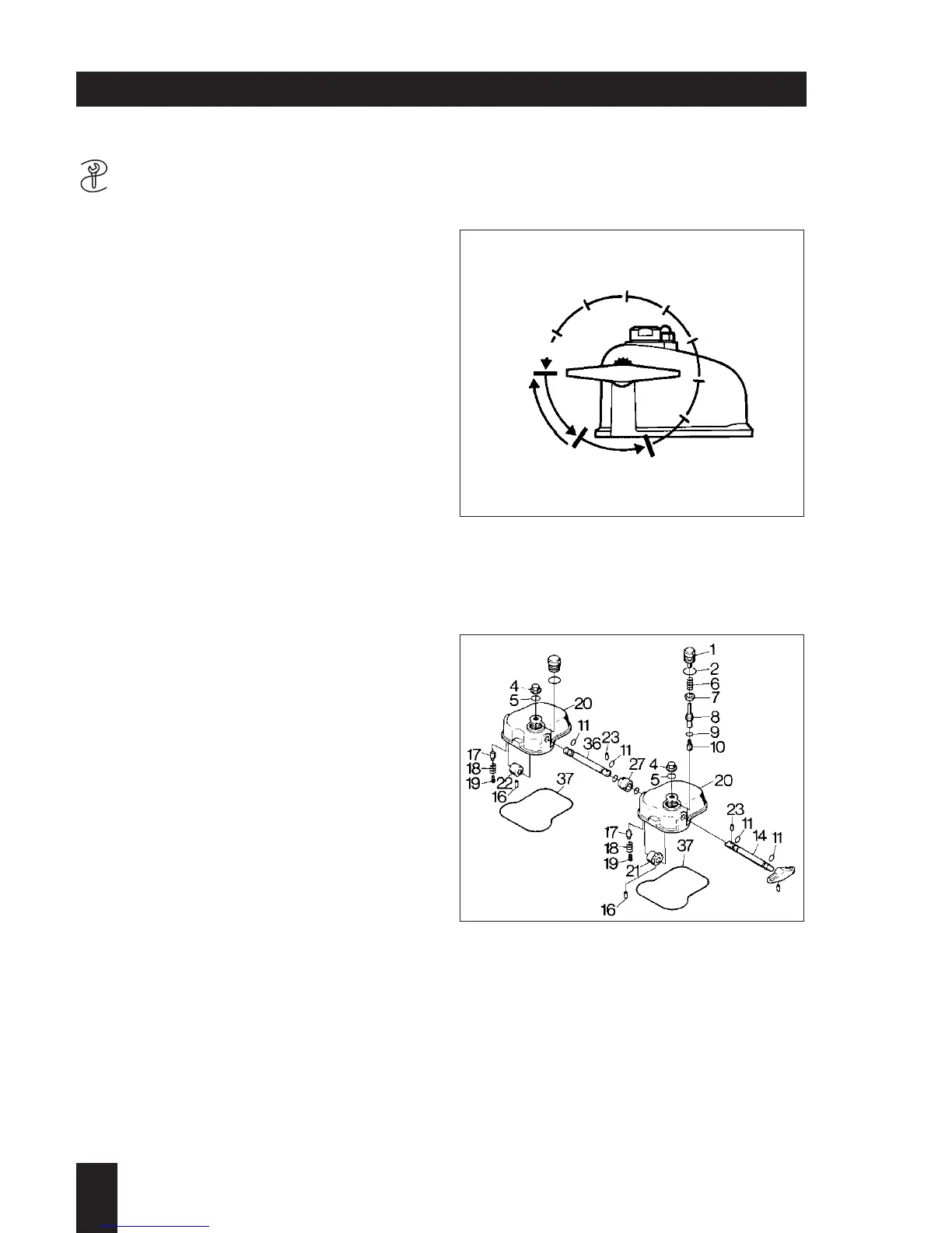
The automatic decompressor has the
following positions; Fig. 93:
0 = Operating position, with engine
running
1 = Permanent decompression, automatic
device switched off
2 = Automatic decompressor switched on,
engine compression is built up auto-
matically after about 8 turns of the
handle.
Detaching:
– Unscrew cap nut (94/4) with sealing ring
(94/5).
– Take off cover (94/20) with gasket
(94/37).
On two-cylinder engines, shafts (94/14)
and (94/36) are connected together by
coupling sleeve (94/27) and 2 locking
collets (94/23). Camwheel (94/22) is then
used at the second cylinder (flywheel
side) instead of the gearwheel.
Dismantling the automatic decompres-
sor:
– Unscrew and remove screw plug (94/1).
– Take out sealing ring (94/2), spring
(94/6), cap (94/7) and lifting pin with
shims and pressure pin (94/8, 9, 10).
– Unscrew threaded rod (94/19) and
remove spring (94/18) and pressure pin
(94/17).
– Using a suitable split-pin driver, drive
locking collet (94/16) about 3 mm into
gearwheel (94/21).
– Turn the gearwheel through 180° and
pull the locking collet out with pliers.
– Take out shaft (94/14) and gearwheel.
2
L / M . . 09.96
93
94
A 04.00 Start mechanical
A 04.20 Automatic decompressor (M 31, M 40, M 41)
 Loading...