USE ONLY HAYWARD GENUINE REPLACEMENT PARTS
4
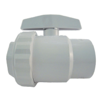
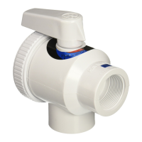
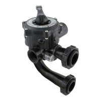
(3) 1/4” NPT x 3/8” Tubing True-Seal Ball Valve
(1) Flow Switch with 24” Cable and Specialty Connector
(1) Temperature Sensor with 10’ Cable and Specialty Connector
(1) Satellite Antenna w/ Base and 35’ Cable
(2) BNC Connector Protective Covers (Remove to Connect Sensors)
(1) 30’ Roll, Blue Poly Installation Tubing (3/8” OD)
(2) 1/4” NPT x 3/8” Tubing True-Seal Connectors
(1) CAT 5000 Quick Reference Guide
NOTE: Before commencing installation, please confirm that items listed above have been included.
Please report any shortages immediately to the factory.
What You Will Need:
The following tools are recommended for installation:
Drill (Cordless preferred)
3/8” Drill Bit
1/4” NPT (National Pipe Tapered) Tap
Masonry Drill Bit & Anchors (if required)
13/16” Wrench or Channel-Lock Pliers.
Installation
Installation Procedure:
The key to a successful flow cell installation is in the plumbing. A pressure differential is required to
allow clean, untreated water to pass through the cell and across the sensors. We recommend using
the enclosed tubing and fittings to create a pressure-suction “loop” line.
Follow the directions below for installation and refer to the Installation Diagram on page 6.
1. Turn off heater, chemical feeders, pump, and any other related equipment. Relieve pressure
from filtration system.
2. Select a convenient mounting location for the controller unit which will meet the following
criteria:
a. Facilitates a combined (influent and effluent) maximum tubing run of 30’.
b. Located a minimum of ten feet from pool or spa.
c. GFI protected power source available.
d. Easily accessible to pool or spa operator.
e. Away from corrosive materials and physical hazards.
3. Securely mount PVC Backboard on vertical wall.
4. Drill and tap a 1/4” NPT port at a location just downstream of the filter, but upstream from
any chemical injection point. Install a tubing connector, and run flex tubing to the influent
flow cell port.
5. Drill and tap a 1/4” NPT port at a location subject to vacuum or reduced pressure. Install the
remaining tubing connector and run flex tubing to the effluent flow cell port.
 Loading...