8
SECTION 3. INSTALLATION
Outdoor installation and venting:
The following installation and service clearances must
be maintained from surfaces to provide adequate air ow to
the heater.
1. Outdoor models with integral vent or HWS vent are
self-venting and do not require additional vent piping.
2. Do not install in a location where growing shrubs may in time
obstruct a heater’s combustion air and venting areas.
3. When locating an outdoor model consider that high winds can
roll over or deect off adjacent buildings, walls, and shrubbery
to create a negative draft causing ame rollout and soot-
ing, reducing combustion efciency and damaging controls.
Normally, placing the heater at least 2 feet from any wall will
prevent this condition.
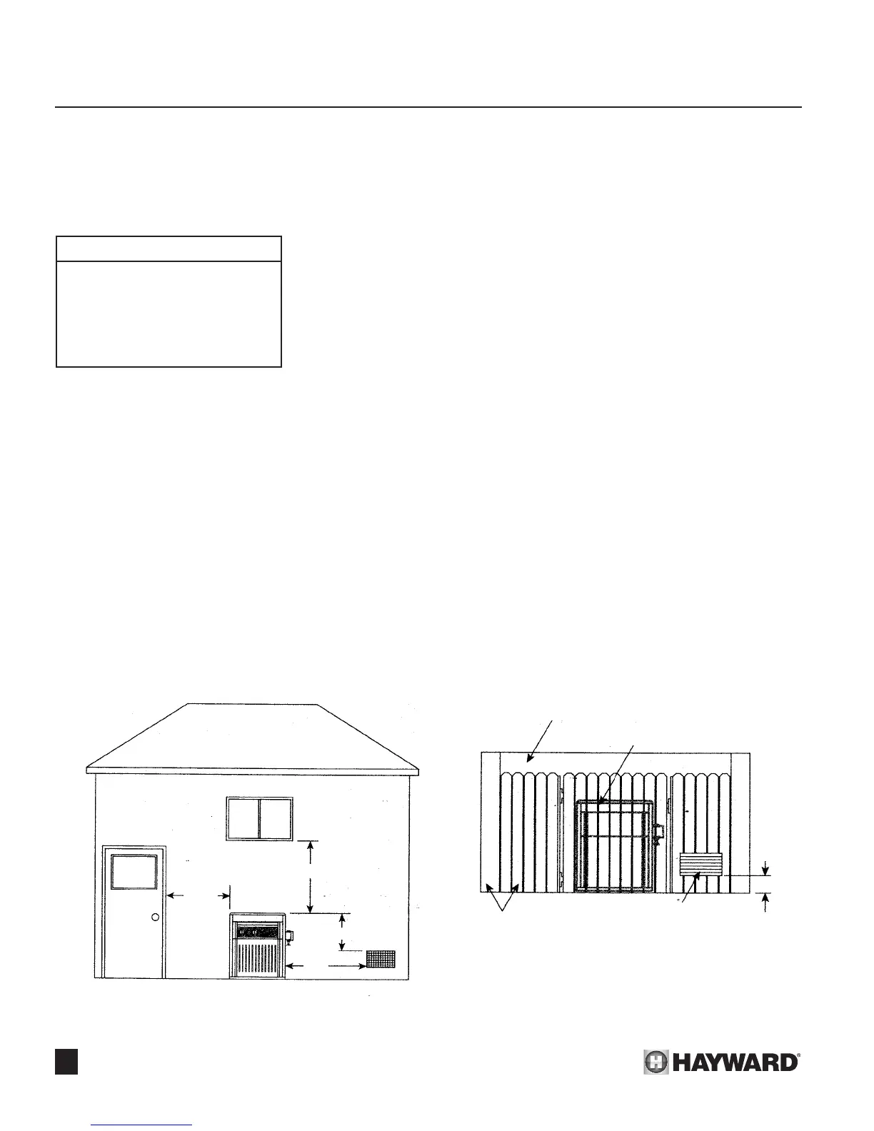
4. The venting system shall terminate at least 4 feet below, 4
feet horizontally from, or 1 foot above any door, window, or
gravity air inlet into any building. The bottom of the vent termi-
nal shall be located at least 12 inches above grade.
A venting system shall terminate at least 3 feet above any
forced air inlet located within 10 feet. See Figure 10.
! WARNING: (Canadian Installations Only) - The venting
system shall not be installed with the top of the vent assembly
within 10 feet below or to either side of any opening into the
building.
5. Do not install this appliance under an overhang less than 3
feet from the top of the appliance. The area under the over-
hang must be open on three sides.
6. Do not install heater directly under a roof overhang edge that
is not equipped with a rain gutter. Cascading rain water off the
roof edge could otherwise cause pilot outage or other operat-
ing problems.
7. Do not install heater where water spray from ground sprinklers
can contact heater. Sprinkler water could cause pilot outage
or other operating problems.
8. Do not install within 3 feet of an air conditioning condens-
ing unit. Blown air from a condensing unit adjacent to heater
could cause pilot outage, poor combustion, or other operating
problems.
9. Do not install under a deck.
10. Any enclosure around the heater must provide a combustion
air vent commencing within 12 inches of the bottom of the
enclosure. The vent opening shall have a minimum free area
of 1 square inch per 4,000 BTU per hour of total input rating
of all heaters in the enclosure. See Figure 11.
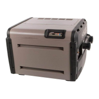
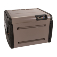
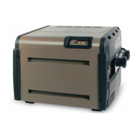
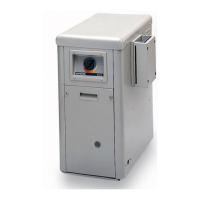
Figure 9
Outdoor Installations
Top - Open and unobstructed
Front - Unobstructed
Back - 6”
Non-combustible oor
Right side (Water side) - 12”
Left side - 6”
Figure 10: Outdoor Installation Figure 11: Outdoor Enclosure
4’ MIN.
4’ MIN.
3’ MIN.
10’
MIN.
FORCED
AIR
INTAKE
OPEN OR GRATED TOP
HEATER INSIDE ENCLOSURE
COMBUSTION
AIR VENT
OUTDOOR
EQUIPMENT ENCLOSURE
(BLOCK WALL
OR OTHER FENCING)
12”
OR
LESS
 Loading...