20
SECTION 4. INSTALLER CHECKOUT & START-UP
7. If the gas pressure does not meet the above require-
ments the regulator must be adjusted.
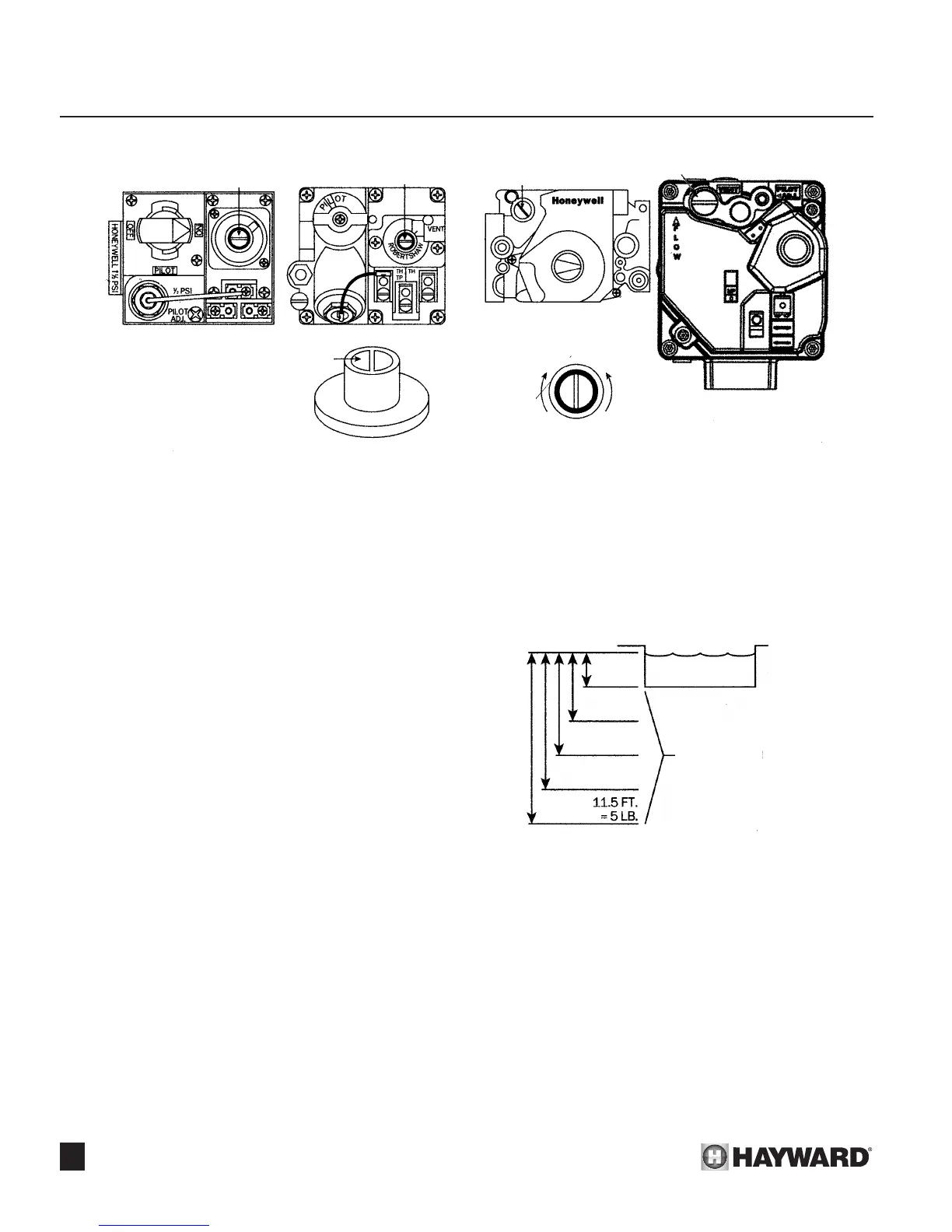
B. GAS PRESSURE REGULATOR
ADJUSTMENT PROCEDURE:
1. Remove access screw from the pressure regulator.
2. Turn regulator adjustment screw clockwise to increase
pressure and counterclockwise to decrease pressure.
Replace access screw. See Figure 36.
! SAFETY WARNING: Do not remove the 1/8” pipe nipple with
the valve in the “ON” position. The valve must be in the “PILOT”
or “OFF” position when the plug is removed.
3. Remove 1/8” pipe nipple and replace 1/8” plug. If proper
pressure cannot be achieved by adjusting the regulator,
the installer must contact the gas supplier and request
that the inlet pressure to the heater be set as follows:
Natural gas - 7” W.C., Propane gas -11” W.C. The inlet
gas pressure must not exceed 10.5” W.C. (water col-
umn pressure) for Natural gas or 13” W.C. for Propane
gas. Exposure to higher pressures can damage the gas
control valve, causing leaks or diaphragm rupture. This
damage could result in re, explosion or burner overring
leading to carbon monoxide poisoning. Minimum inlet gas
pressure is 5.0”W.C. for Natural and 10” W.C. for Propane
for the purpose of input adjustment.
INSTALLATION BELOW
POOL/SPA SURFACE:
1. Clean lter thoroughly.
2. Set heater thermostat to highest setting.
3. Start lter pump. Make sure all air is out of water lines and
complete system is full of water.
4. Turn lter pump off, adjust pressure switch control. (See
“Pressure Switch” on Page 32.)
5. Check pressure switch function by turning lter pump on and
off causing heater to respond on or off. If heater is installed
beyond pressure limits, a ow switch must be installed in
water line to heater.
TWO SPEED PUMP:
In a few cases, the pressure from a two speed pump is below
the one pound minimum required to operate the heater. This is
apparent when the pressure switch cannot be further adjusted.
In these cases the pump must be run at high speed to operate
heater. If the pump and piping arrangements are such that the
required one pound minimum pressure cannot be obtained, do
not attempt to operate the heater. Correct the installation.
Heater installation, check-out and start-up should now
be completed. BE SURE to leave Installation, Operation &
Service Procedures Manual with consumer.
Figure 36: Valve Adjustment Screw
Figure 37: Heater Installation Below Pool
HONEYWELL
HONEYWELL
ROBERTSHAW
ADJUSTMENT
SCREW
ACCESS SCREW
OFF
ON
ON
ON
OFF
OFF
INCREASE
PRESSURE
DECREASE
PRESSURE
ADJUSTMENT
SCREW
ADJUSTMENT SCREW WHITE-RODGERS 36H
ADJUSTMENT
SCREW
HONEYWELL
MILLIVOLT ELECTRONIC
WATER LEVEL
2.3 FT.
= 1 LB.
4.6 FT.
= 2 LB.
6.9 FT.
= 3 LB.
9.2 FT.
= 4 LB.
1 FT. HEIGHT = 0.4331 LBS.
1 LB. = 2.31 FT. HEIGHT
HEATER
INSTALLATION
LEVELS
 Loading...