1. Remove black metal Trim Plate (around water manifold, 5 Black screws)
2. Remove water connection side Upper End Cap (Black Polymer- 4 screws in
rectangle holes marked with an arrow)
3. Disconnect Unions from plumbing (water connections, 1 inlet, 1 outlet.)
4. Remove (8) ½” hex head bolts ( 4 on each side-inlet and outlet)
5. Remove water manifold (also called the “Header”) and black polymer
“Mounting Blocks” to expose the ends of the heat exchanger tubes.
6. If there is any doubt as to whether or not there is damage from aggressive
water chemistry: take 3 pictures, 1 of each pair of tubes (inlet side and outlet
side), as well as the Model & Serial number decal, and send to your local
technical representative, or call (908) 355-7995 for further instructions.
62
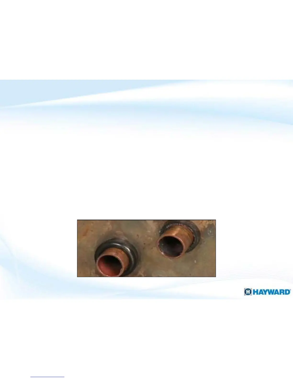
Heat Exchanger: Inspection
Heat Exchanger tubes should look like this picture
 Loading...