If the indicator flickers, the system works
normally.
PoE indicator
corresponding to
each port
If the indicator is always on, the PoE works
normally.
If the indicator is off, the PoE does not work.
Lnk/Act indicator
corresponding to
each port
Green indicator is on: 10/100M is
transmitted;
Red indicator is on: 1000M is transmitted;
No indicator is on: no signal is transmitted.
Realizes the PoE function and forwards
10/100/1000M Ethernet electrical signals
Manages the switch locally.
Realizes the forward of gigabit Ethernet
optical signals.
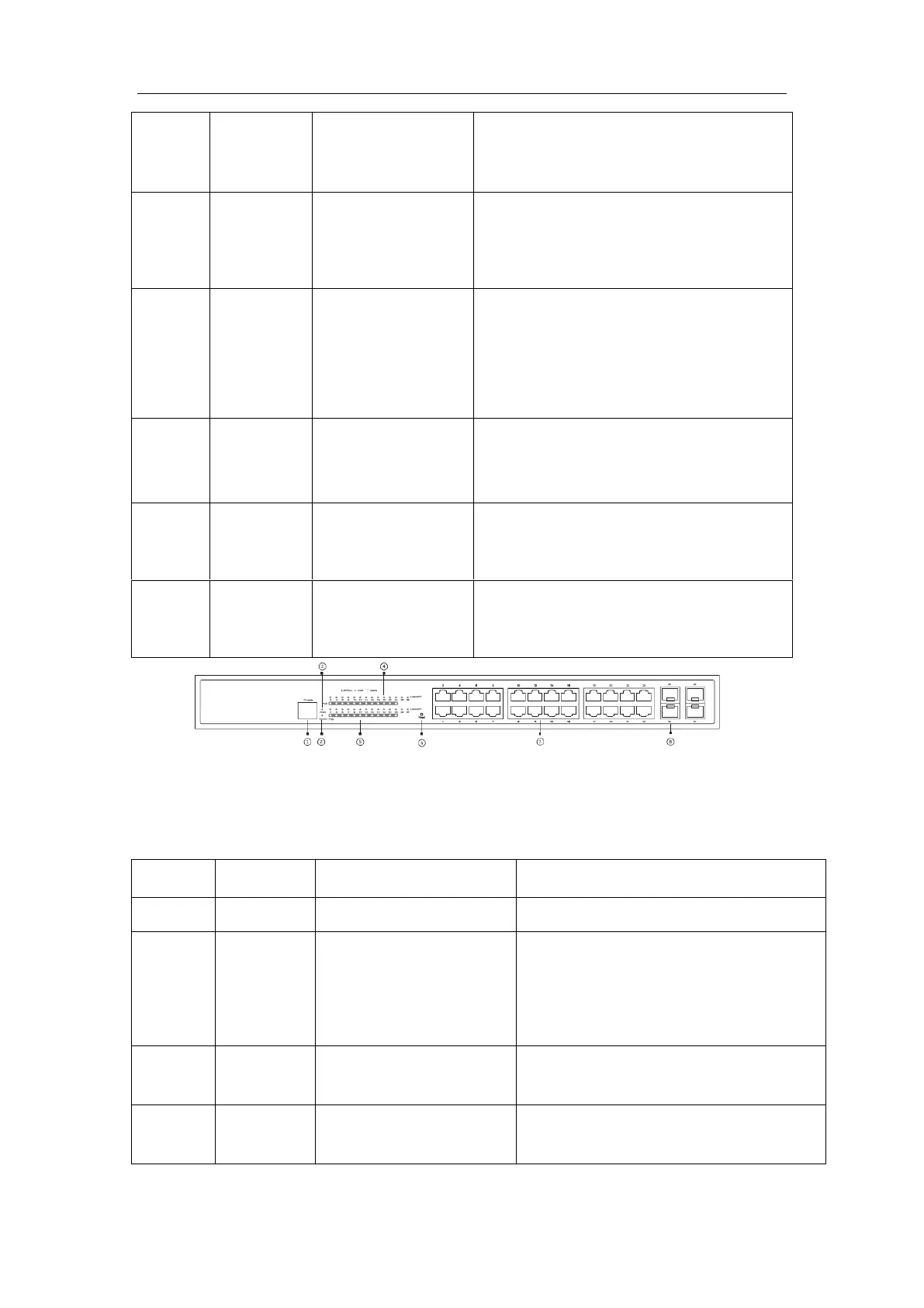
Figure 1-2 Front template of the 24 switch
Table 1-3 Parts at the front template of the 24 switch
Manages the switch locally.
If the indicator is always on, the system
is being started.
If the indicator flickers, the system works
normally.
If the switch is powered on, the indicator
is on.
LINK/ACT indicator of
each port
If the indicator is on in green: 10/100M,

 Loading...