Quick Operation Guide of DS-9600/8600/7600NI-ST Series NVR
12
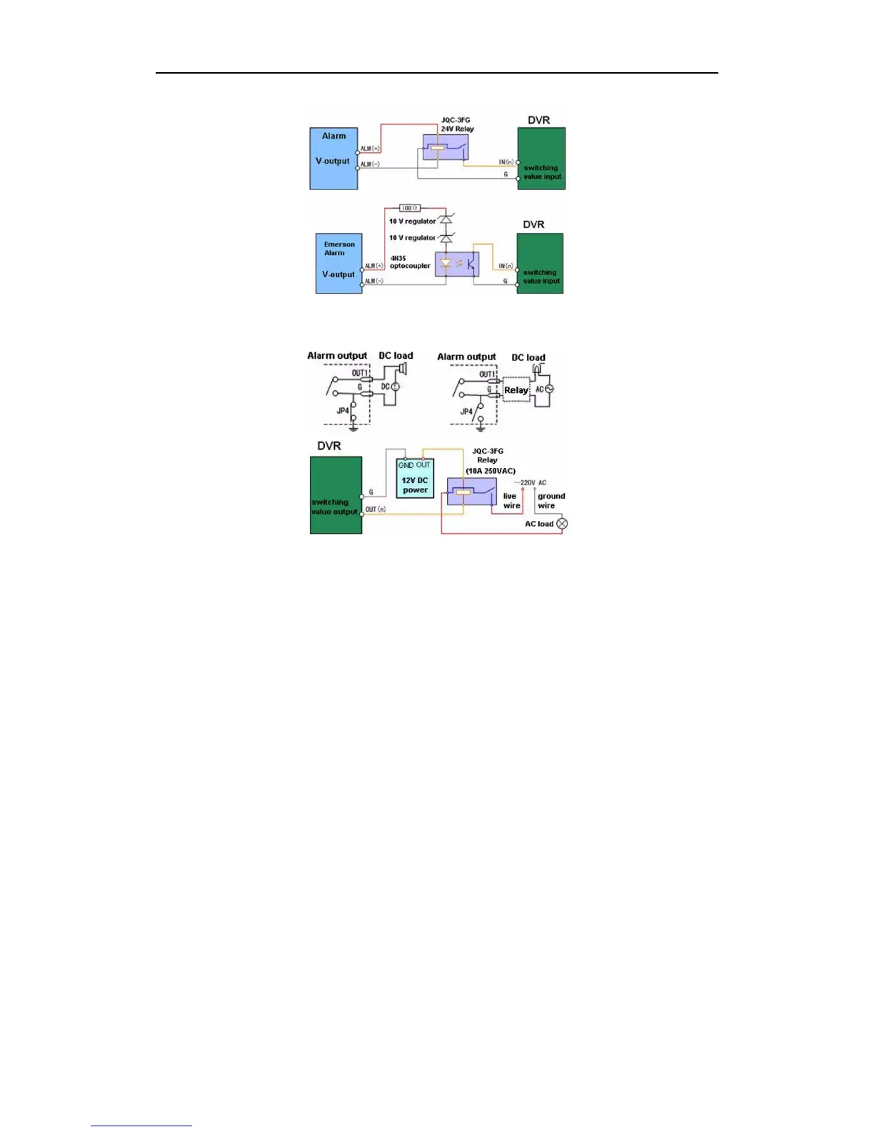
To connect to an AC/DC load, use the following diagram:
For DC load, JP4 can be used within the limit of 12V/1A safely. If the interface is connected to an AC load, JP4
should be left open. Use an external relay for safety (as shown in the figure above).
There are 4 jumpers (JP4, JP5, JP6, and JP7) on the motherboard, each corresponding with one alarm output. By
default, jumpers are connected. To connect an AC load, jumpers should be removed.
Note: An external relay is needed to prevent electric shock when connecting to an AC load.
Alarm Connection
To connect alarm devices to the NVR:
1. Disconnect pluggable block from the ALARM IN /ALARM OUT terminal block.
2. Unfasten stop screws from the pluggable block, insert signal cables into slots and fasten stop screws. Ensure
signal cables are in tight.
3. Connect pluggable block back into terminal block.
RS-485 Connection
In this manual we take the RS-485 connection of the DS-8600NI-ST as an example.
 Loading...