Video Intercom Door Station·User Manual
57
2. Select I/O input No., input mode, output No., and output mode.
3. Click the Save button to enable the settings.
For door station (D series), there are 8 I/O Input Terminals. Terminal 1~4 correspond
to SENSOR interfaces (S1, S2, S3, S4) of door station. Terminal 5~8 correspond to
interfaces of ALARM IN (A1, A2, A3, A4). You can select an I/O input No. (S1, S2, S3, S4,
AI, A2, A3, A4) from the drop-down list and set the I/O input as door magnetic exit
button.
For door station (V series), there are 4 I/O Input Terminals, corresponding to SENSOR
interfaces (S1, S2, S3, S4) of door station.
For door station (D series and V series), there are 4 I/O Output Terminals.
Terminal 1~2 correspond to DOOR interfaces (NO1/COM1/NC1; NO2/COM2/NC2) of
door station. You can enable/disable IO Out by selecting from the dropdown list.
Terminal 3~4 correspond to interfaces of ALARM OUT (AO1+, AO1-; AO2+, AO2-).
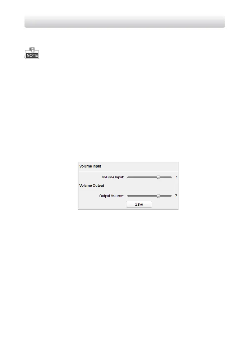
Volume Input and Output
Step:
1. Click Volume Input/Output button to enter the volume input and output interface.
Figure 8-28 Volume Configuration
2. Slide the slider to adjust the volume input and volume output.
3. Click the Save button to enable the settings.
8.4.3 Network
Local Network Configuration
Steps:
1. Click the Local Network Configuration button to enter local network configuration
interface.
 Loading...