X-CPU 01 3 Product Description
HI 801 009 E Rev. 4.00 Page 21 of 52
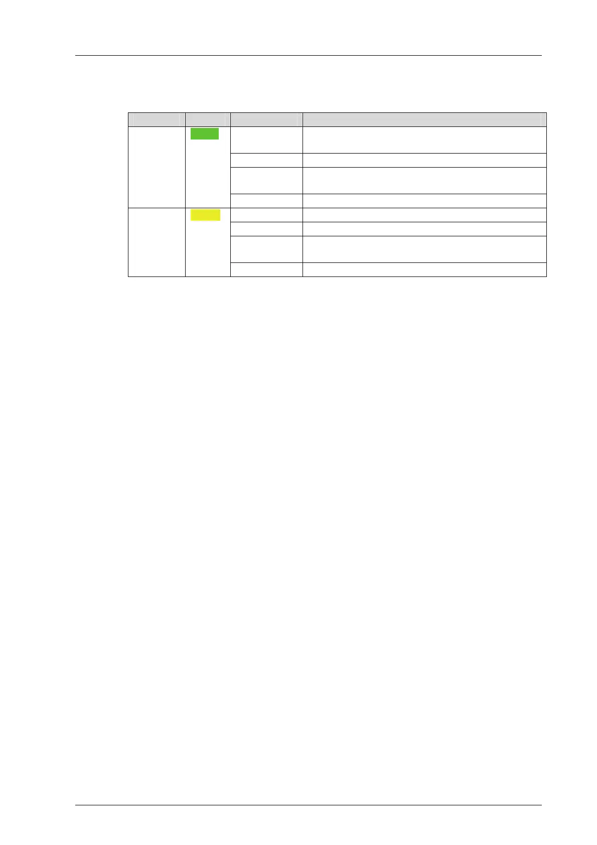
3.4.17 Ethernet Indicators
The Ethernet LEDs are labeled Ethernet.
LED Color Status Description
On Communication partner connected
No communication detected on interface
Blinking-x Communication detected on interface.
Blinking1 IP address conflict detected
All Ethernet LEDs are blinking
Eth 1…4 Green
Off No communication partner connected
On Full duplex operation on Ethernet line F
Blinking-x Collisions detected on Ethernet line Col
Blinking1 IP address conflict detected
All Ethernet LEDs are blinking
H/F/Col
1…4
Yellow
Off Half duplex operation on Ethernet line H
Table 11: Ethernet Indicators
3.4.18 Mode Switch
The mode switch defines how the processor module behave when restarted.
The processor module is restarted in the following cases:
Automatically:
- When connecting the operating voltage
- After a severe failure
- After loading the operating system
During operation, using the corresponding command on the PADT.
The mode switch has three different switch positions:
Init
Stop
Run
The switch position during normal operation is Run.
Switch Position: Init
The Init switch position is used to set the processor module to the LOCKED states. In this
state, the settings previously configured for the module can no longer be accessed. This
can be required if, for instance, the administrator password is unknown.
In the LOCKED state, the module is reset to the factory settings:
Default SRS, the slot number depends on the slot used
Default IP address and IP settings
Only accessible for Administrator user account with empty password
Enabling switches set to default values
Setting values that are are modified in this state overwrite the factory settings and all the
settings previously used!
If the settings remain unchanged, the previously saved settings are used when the module
is restarted (the switch is not set to Init).

 Loading...