8
AV3000 AVC Unit Service Manual
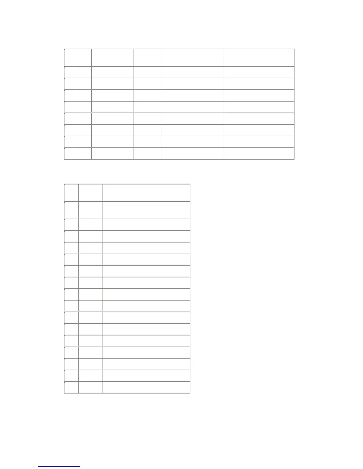
4.4.2.
M62320FP
I/O expanders (IC09)
Pin
No.
Pin
Name
Description Connect to L H
4 D00 Component video IC02, IC05 Components input Other than components
5 D01 Matrix IC02 RGB --> YUV Through
6 D02 PC IC07 Not PC mode (SUB TEXT) PC mode (SUB video in PCW)
7 D03 OSD-blank IC03 Kill OSD OSD enabled
9 D04 Cinema IC06, IC04 Audio centre not selected Audio centre selected
10 D05 Clamp-source IC05 CP from TA1370 SC from TDA9321
11 D06 TV/TEXT IC03 TEXT (select RGB input) TV
12 D07 N.C.
4.5. Power Circuit/Level Shifter (Schematic Sheet 4)
Power Supply Connector PSP from Power Supply board:
Pin
No.
Pin
Name
Remarks
1 POWER1
Power ON/Stand-by control
H: ON, L: Stand-by
2,3,4 N.C.
5 +5VSTB Stand-by 5V for micro controller circuit
6 GND
7,8 N.C.
9 GND
10 GND
11 +5.5V1 5.5V supply 1
12 GND
13 +9.5V1 9.5V supply 1
14 GND
15 +5.5V2 5.5V supply 2
16 GND
17 +9.5V2 9.5V supply2
18 GND
19 FE+30V 30V supply for tuner
 Loading...