--- 23 ---
9. ADJUSTMENT OF COMPONENTS
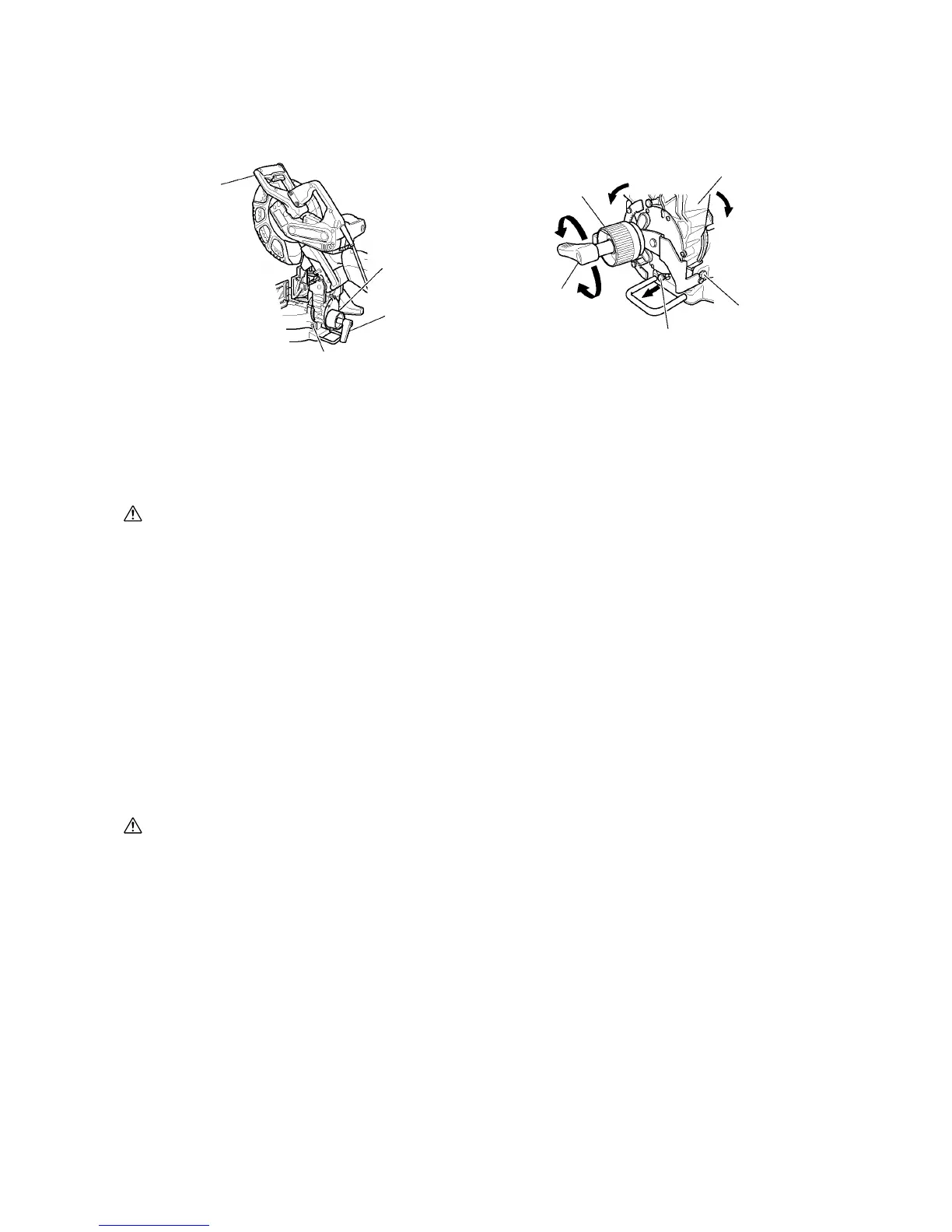
9-1. Bevel Angle Fine Adjustment
Fig. 37-a Fig. 37-b
8 mm bolt (C)
Knob (A)
8 mm bolt (B)
(Stopper for left 45˚ bevel angle)
Handle
Knob (A)
Clamp lever
Clamp lever
Bevel plate
(Stopper for right 45˚ bevel angle)
Left bevel angle
Pull
Hinge
Right bevel angle
(1) Grip the handle on the motor head and position it at the bevel angle you need. Temporarily tighten the clamp
lever.
CAUTION: If not tightened firmly enough the motor head might suddenly move or slip, causing
injuries. Be sure to tighten the motor head section enough so it will not move.
(2) Make fine adjustment to the bevel angle by gripping the handle and moving knob (A).
NOTE: Turning knob (A) clockwise allows fine adjustment of the main unit to the left (as seen from front).
Turning knob (A) counterclockwise allows fine adjustment of the main unit to the right (as seen
from front).
If you wish to cut left bevel angle 48˚ or right bevel angle 48˚, pull the bevel plate backwards until
the hinge contacts either 8 mm bolt (C) or 8 mm bolt (B) then cut diagonally left or right.
Setting to cut left bevel angle 48˚ or right bevel angle 48˚ can be done easily.
(3) After adjusting to the desired angle, tighten the clamp lever and clamp the motor head.
CAUTION: Always check that the clamp lever is secured and the motor head is clamped. If you
attempt angle cutting without clamping the motor head, then the motor head might shift
unexpectedly causing injuries.
 Loading...