--- 42 ---
11-9. Adjustment of Laser Marker Accuracy
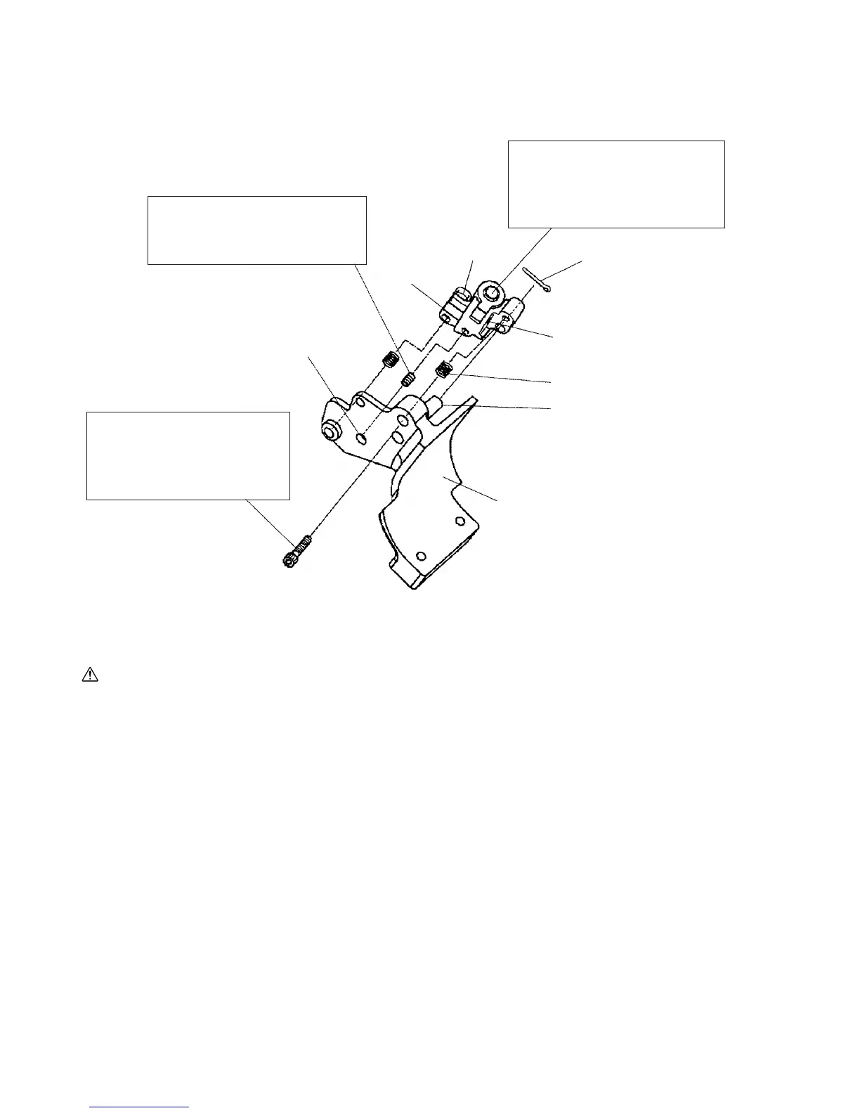
(1) Construction of laser marker and functions of each component
Fig. 58
CAUTION: Exercise utmost caution in handling a switch trigger for the position adjustment of the laser
line, as the power plug is plugged into the receptacle during operation. If the switch trigger
is pulled inadvertently, the saw blade can rotate and result in unexpected accidents.
Do not stare into beam while the laser marker is lighting. Do not observe beam directly
with an optical instrument. If your eye is exposed directly to the laser beam, it can be hurt.
Instruct the customer not to stare into beam. In addition, instruct the customer not to give
strong impact to the laser marker (main body of tool) and not to dismantle the laser marker.
Use of controls or adjustments or performance of procedures other than those specified in
this TECHNICAL DATA AND SERVICE MANUAL and the Instruction Manual may result in
hazardous radiation exposure.
Laser
Holder (B) [4]
Spring (C) [6]
Roll Pin D3 x 14 [5]
Split Pin D2 x 12 [3]
Needle pin
Laser Base Ass'y [10]
Hex. bar wrench
(2.5 mm) inlet
Spring (B) [1]
Hex. Socket Set Screw M5 x 6 [7]:
The squareness between the laser
line and the fence surface can be
adjusted by turning this screw.
Laser Holder (A) [2]:
The squareness between the laser
line and the base surface can be
adjusted by turning the minus
groove at the rear.
Special Bolt M5 [8]:
The laser line can be aligned
with the left side or the right side
of the cutting width (saw blade)
by turning this bolt.
 Loading...