--- 24 ---
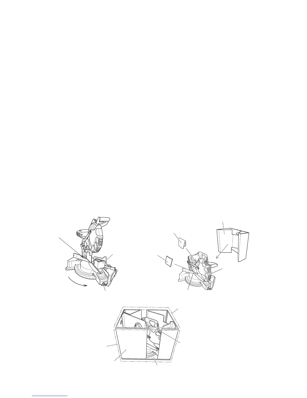
10. PACKING
(1) Preparation before packing
(i) Remove the dust bag from the main body.
(ii) Turn the turn table 48˚ clockwise and remove the side handle. Secure the turn table with the attached hex.
socket head bolt M10.
(2) Mounting packing (C)
(i) Place packing (C) under the gear case and lower the head section. Pressing on packing (C), insert the
stopper pin of the gear case to secure the head section. (At this time, check that the clamp lever for bevel
angle fixation is securely locked.)
(3) Mounting packing (D)
(i) Fold packing (D) in two at the center and insert it between the gear case and the protective cover.
(4) Mounting packing (E)
(i) Insert packing (E) between sub fence (B) and the gear case.
(5) Mounting packings (A) and (B)
(i) Place the base packing and the sleeve in the carton box and place the power tool on them aligning with the
concave portion of the base packing.
(ii) Place packing (B) aligning the hole of packing (B) with the housing.
(iii) Place packing (A) in the carton box.
(6) Mounting upper packing
(i) Place the upper packing on packings (A) and (B). Close the carton box. See Figs. 38, 39 and 40 for detail.
Clamp lever
for bevel
angle fixation
Fig. 38
Upper packing
Fig. 40
Turn by 52˚.
Hex. socket head bolt M10
Packing (C)
Protective
cover
Packing (D)
Packing (A)
Lower the
head
section.
Sub fence (B)
Packing (E)
Fig. 39
Packing (B)
Carton box
Base packing
Sleeve
 Loading...