--- 6 ---
7. PRECAUTIONS IN DISASSEMBLY AND REASSEMBLY
The [Bold] numbers in the descriptions below correspond to the item numbers in the parts list and exploded
assembly diagram.
7-1. Disassembly
(1) Disassembly of the fan
Be sure to draw on work gloves before holding the Fan [7] to prevent injury to fingers. Remove Nozzle Ass'y
(A) [1] from the main body. Remove the Tapping Screws (W/Flange) D4 x 20 (Black) [9] and the Tapping
Screws (W/Flange) D4 x 25 [35] that secure the Casing Cover [5] to the casing. Remove the U-Nut M6 [6]
and pull out the Fan [7] from the armature shaft.
(2) Disassembly of the armature
After removal of the Fan [7], remove the Carbon Brushes (1 Pair) [28] from the Housing Ass'y [20]. Remove
the Tapping Screws (W/Flange) D5 x 30 [10] that secures the casing to the housing ass'y. After removal of the
Casing [8] from the Housing Ass'y [20], the Armature [15] can be removed together with the Casing [8] or the
Armature [15] is remained in the Housing Ass'y [20]. In either case, the Armature [15] can be removed by
lightly tapping the end of the Casing [8] or the Housing Ass'y [20] with a wooden hammer.
(3) Disassembly of the armature
Remove the Tapping Screws (W/Flange) D4 x 20 (Black) [9] that secures the Handle Cover [23] to the
Housing Ass'y [20]. Loosen the screw securing the cord of the Switch (1P Pillar Type) [24] and remove the
cord.
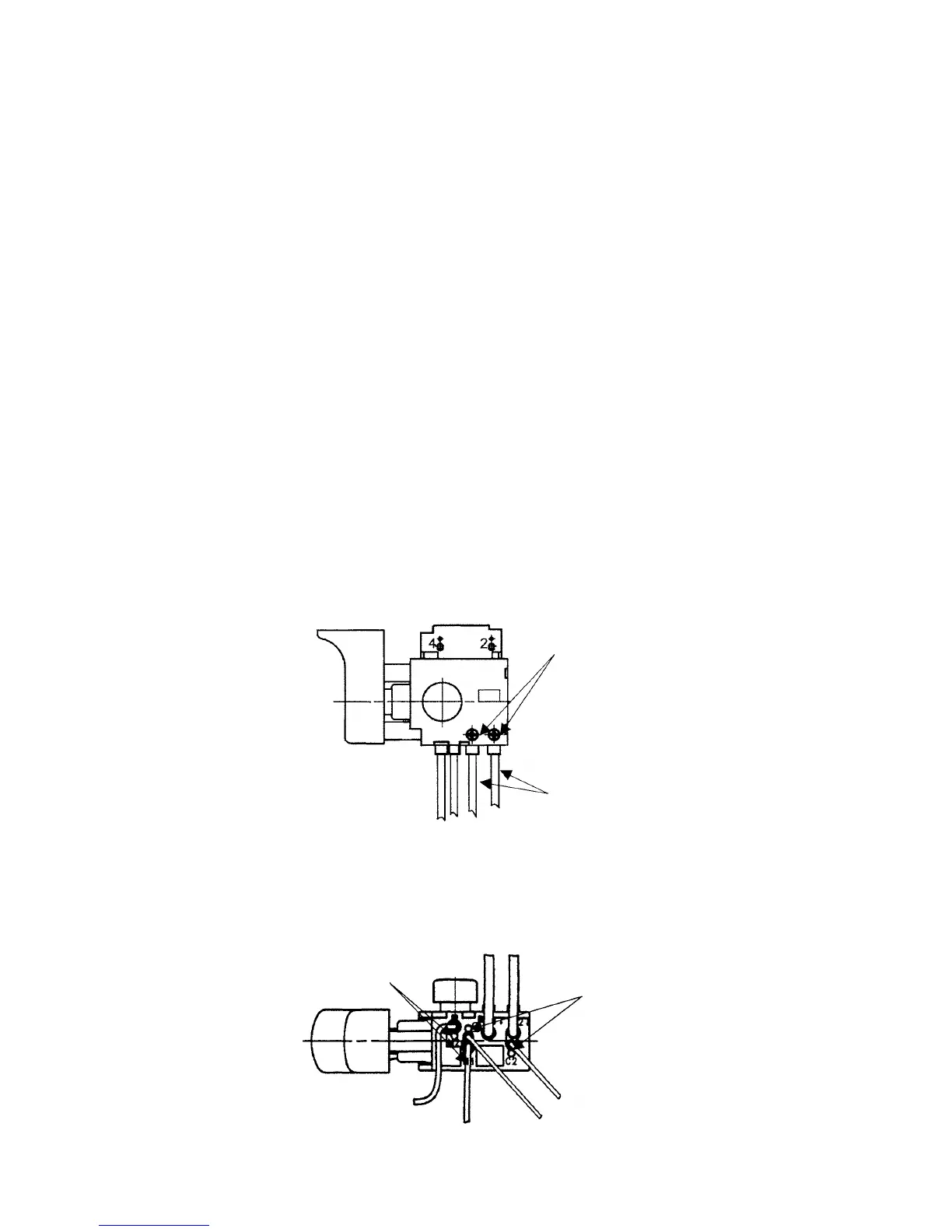
Fig. 5
Screw securing the cord
Cord
Fig. 4
Remove the internal wire or the choke coil of the Stator Ass'y [18] and the internal wire of the Noise
Suppressor [30] by inserting a small-diameter screwdriver or a pin into the indentations adjacent to each
terminal and pulling the internal wires lightly.
Indentations
Indentations
 Loading...