EasyManuals Logo
Home>Hitachi>Inverter>S1 Series

Hitachi S1 Series User Manual

Hitachi S1 Series
235 pages
To Next Page IconTo Next Page
To Previous Page IconTo Previous Page
Page #19 background imageLoading...
Page #19 background image
S1 series standard inverter
-14-
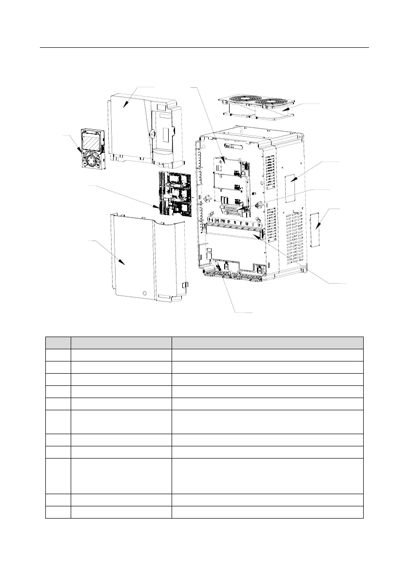
3.7 Structure diagram
The inverter layout is shown in the figure below (take a 400V 30kW inverter as an example).
9
6
8
10
1
2
3
4
11
7
5
Fig 3.8 Structure diagram
No.
Name
Instruction
1
Upper cover
Protect internal components and parts
2
Keypad
See details at chapter 5.4 Keypad operation
3
Lower cover
Protect internal components and parts
4
Control terminals
See details at chapter 4 Installation guide
5
Baffle of control board
Protect the control board and install extension card
6
Cooling fan
See details at chapter 8 Maintenance and hardware fault
diagnosis
7
Nameplate
See details at chapter 3.4 Product nameplate
8
Keypad interface
Connect the keypad
9
Cover plate of heat emission
hole
Optional. Cover plate can upgrade protection level,
however, as it will also increase internal temperature,
derated use is required.
10
Main circuit terminal
See details at chapter 4 Installation guide
11
POWER indicator
Power indicator

Table of Contents

Questions and Answers:

Question and Answer IconNeed help?

Do you have a question about the Hitachi S1 Series and is the answer not in the manual?

Hitachi S1 Series Specifications

General IconGeneral
BrandHitachi
ModelS1 Series
CategoryInverter
LanguageEnglish

Related product manuals