S1 series standard inverter
-26-
The screw is
not fastened.
The screw is
fastened.
YNG
Fig 4.17 Screw installation diagram
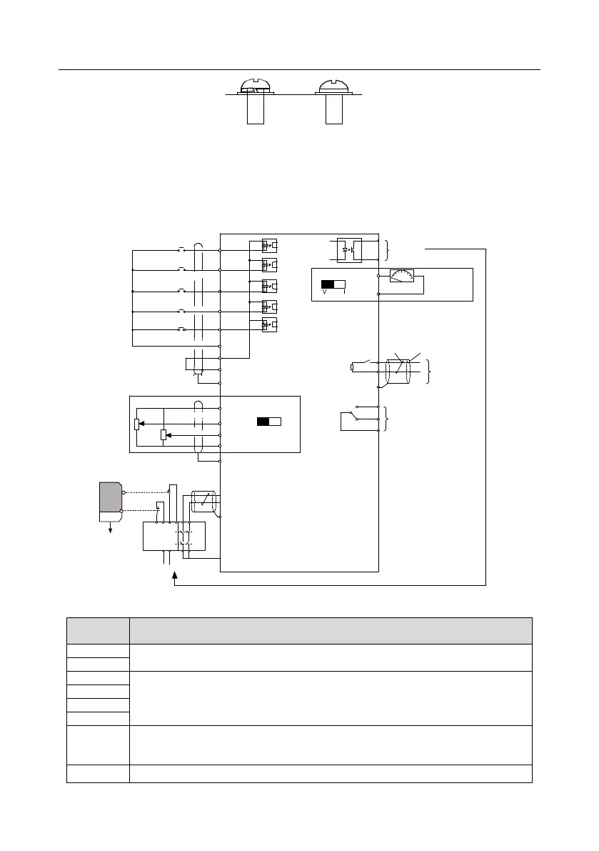
4.4 Standard wiring of control circuit
4.4.1 Wiring diagram of basic control circuit
+24V
COM
Multi-function input terminal 1
Multi-function input terminal 2
Multi-function input terminal 4
High speed pulse input terminal
Multi-function input terminal 3
Y1 output
Analog output
Relay 1 output
Shieldlayer
Twisted pair
PE
PE
S2
H1
Safety switch
Safety controller
Open circuit
Safety state feedback
Safety input
S1
H2
+ 24V
PE
PE
0-10V/0-20mA
RS485
communication
485+
485-
RO1A
RO1B
RO1C
AO1
COM
AO1
Y1
COM
S1
S2
S3
S4
HDI
PW
COM
+10V
AI2
AI3
AI2
V
I
Analog input
Fig 4.18 Wiring diagram of control circuit (0.4–2.2kW)
485 communication interface
1. Internal impedance: 3.3kΩ
2. 12 – 30V voltage input is available
3. The terminal is the dual-direction input terminal
4. Max. Input frequency: 1kHz
Except for S1 – S4, this terminal can be used as high frequency input channel.
Max. Input frequency: 50kHz
Duty ratio: 30% – 70%
Provide input digital working power from external to internal
 Loading...