SJ200 Inverter
Inverter Mounting
and Installation
2–7
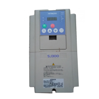
Power Wiring Access - First, ensure no
power source of any kind is connected to the
inverter. If power has been connected, wait
five minutes after powerdown and verify the
Power LED is OFF to proceed. After
removing the front housing cover, the housing
partition that covers the power wiring exit will
be able to slide upward as shown to the right.
Notice the four wire exit slots (on larger
model inverters) in the housing partition. This
helps keep the power wiring (to the left)
separate from signal-level logic or analog
wiring (to the right).
Remove the housing partition and as shown as
set it aside in a secure place while wiring.
Never operate the inverter drive with the parti-
tion removed or the front housing cover
removed.
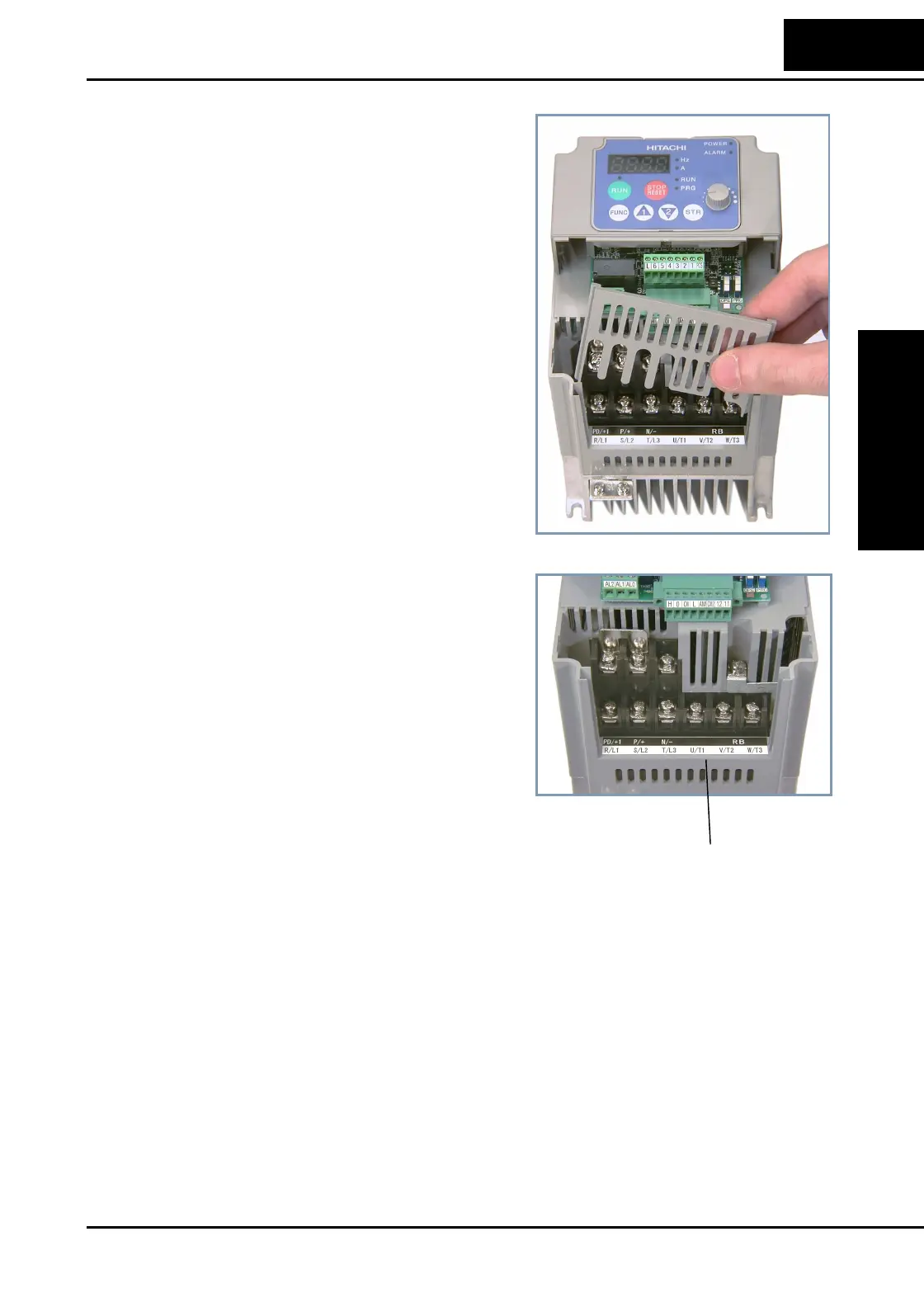
The power input and motor 3-phase wiring
connect to the lower row of terminals. The
upper row of power terminals connect to
optional dynamic braking components.
The following sections in this chapter will
describe the system design and guide you
through a step-by-step installation process.
After the section on wiring, this chapter will
show how to use the front panel keys to
access functions and edit parameters.
Power and motor
connection terminals

 Loading...