CYLINDER BLOCK
14-4
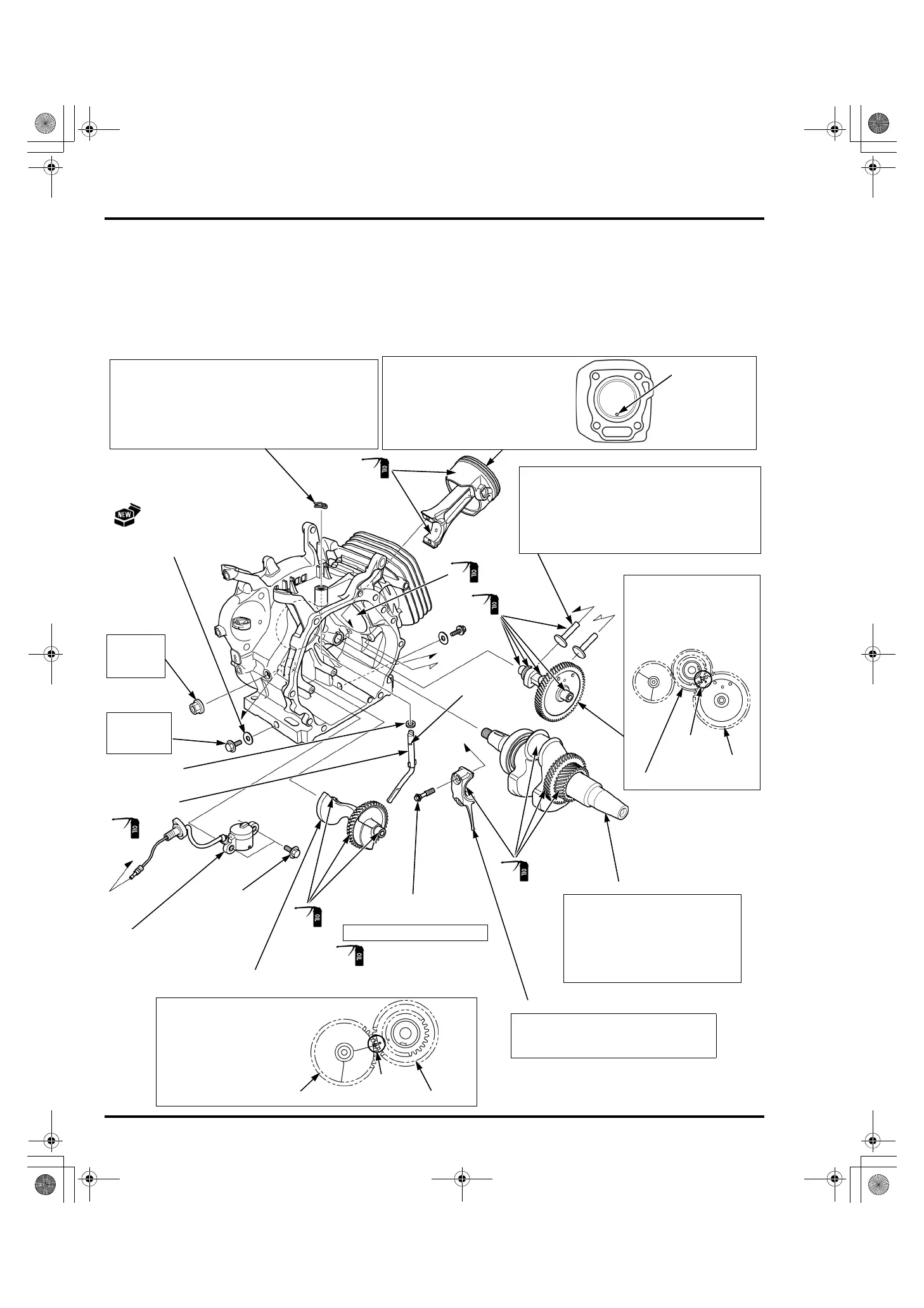
CRANKSHAFT/CAMSHAFT/BALANCER WEIGHT (EXCEPT EG3600/
EG4000)/PISTON REMOVAL/INSTALLATION
Remove the following:
– Flywheel (page 7-10)
– Crankcase cover (page 14-3)
– Cylinder head (page 13-3)
LOCK PIN (10 mm)
PISTON
WASHER
(8.2 x 17 x 0.8 mm)
VALVE LIFTER
CAMSHAFT
CRANKSHAFT
CONNECTING ROD LOWER
CONNECTING ROD
SPECIAL BOLT
BALANCER WEIGHT (Except EG3600/EG4000)
GOVERNOR
ARM SHAFT
DRAIN PLUG
BOLT (2)
INSTALLATION:
Install the piston to the cylinder
barrel with the mark on the piston
head toward the push rod hole of the
cylinder head.
(Viewed from
cylinder head side)
INSTALLATION:
Install the lock pin immediately after installing the
governor arm shaft in the direction as shown.
The lock pin (10 mm) must be installed with the
straight side of the lock pin (10 mm) against the
groove of the governor arm shaft.
22.5 N·m
(2.3 kgf·m,
17 lbf·ft)
14 N·m (1.4 kgf·m, 10 lbf·ft)
INSTALLATION:
Set the connecting rod lower with the oil
dipper toward the camshaft.
INSTALLATION:
Before installing the crankshaft,
check the oil seal of the cylinder
barrel for damage or hardening.
Be careful not to damage the oil
seal when installing the crankshaft.
(Apply to the threads and
seating surface)
OIL LEVEL SWITCH
OIL LEVEL
SWITCH
JOINT NUT
(10 mm)
10 N·m
(1.0 kgf·m,
7 lbf·ft)
groove
BOLT
(6 x 12 mm)
(2)
REMOVAL:
When removing the valve lifters, mark so that the
intake and exhaust sides can be distinguished.
INSTALLATION:
Attach the valve lifters to the cylinder barrel
immediately before installing the camshaft.
INSTALLATION:
Align the punch marks
of the balancer weight
and the crankshaft
(marked on the
balancer drive gear).
INSTALLATION:
Align the punch marks
of the camshaft and the
crankshaft (marked on
the timing gear).
CAMSHAFT
CRANKSHAFT
MARKS
MARK
BALANCER WEIGHT
CRANKSHAFT
MARKS
DRAIN PLUG
WASHER (12 mm) (2)
82Z30000.book 4 ページ 2010年6月25日 金曜日 午後5時50分
 Loading...