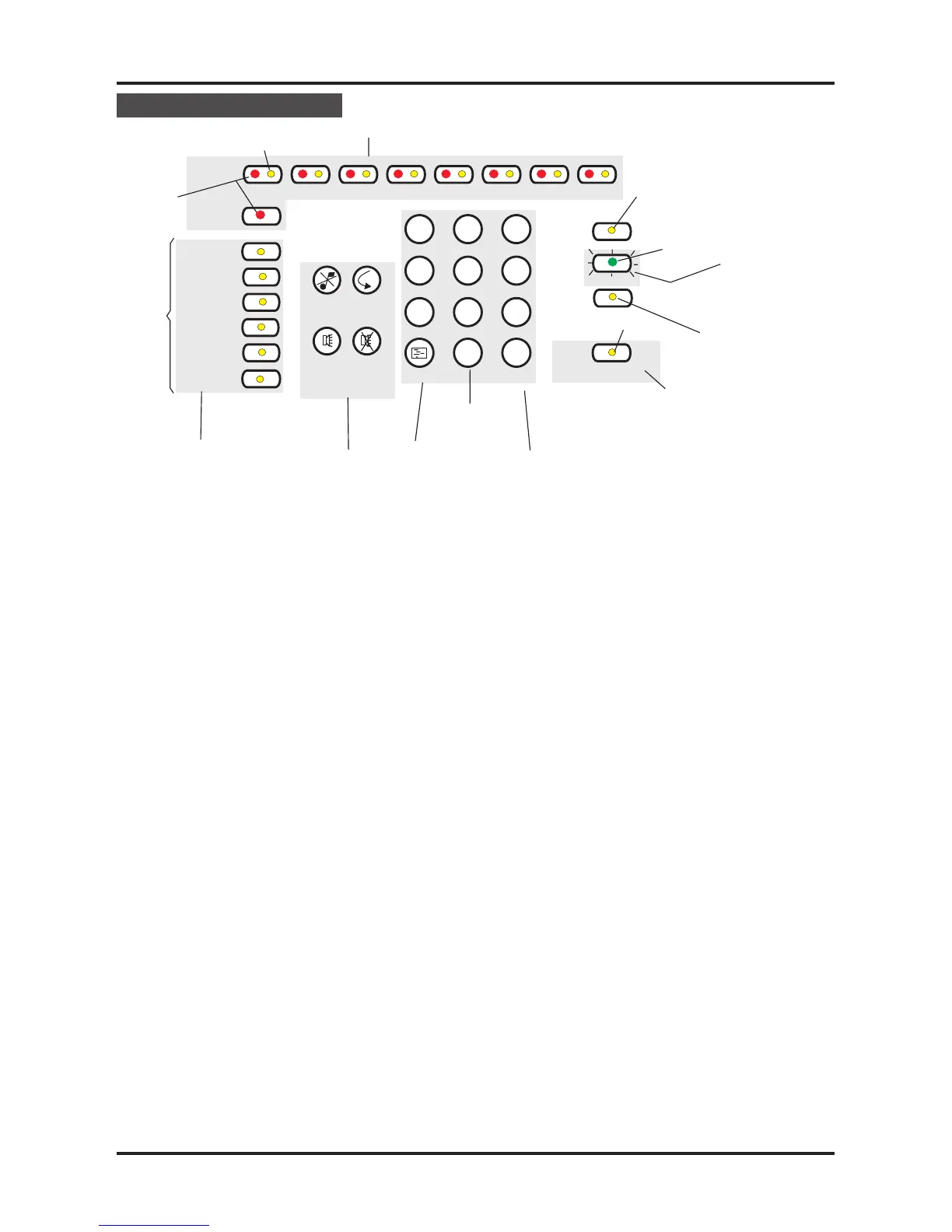
Controls & indicators
Numeric keypad. Allows the entry
of numeric data.
q Shift key. The Shift/Function
key gives access to the main
functions of the panel.
q Display test key. Pressing the
Display Test key after entering
access code# will initiate a
sequence which illuminates all
the indicators in turn enabling
them to be checked.
# Coded entry is only
required if Cancel Buzzer and
Display Test functions are
configured for operation at
Access level 2.
q
Cancel Buzzer. Pressing the
Cancel Buzzer button after
entering access code# will stop
the internal buzzer sounding.
q
System Reset. The system
reset key when pressed after
entering access code will return
the system to its normal
operating state. If there are
uncleared fires or faults then
these conditions will re-occur.
q
Sound Alarms. Pressing the
Sound Alarms button after
entering access code will sound
all of the system alarms. Should
only be pressed in an
emergency or at other agreed
times, ie for sounder tests etc.
Pressing the sound alarms
button does not action the
auxiliary relay.
q Silence Alarms. Pressing the
Silence Alarms button after
entering access code will
silence the system alarms.
Should only be pressed when
the emergency is over.
Indicators.
q
Fire. When lit indicates that the
system has detected a fire.
q
Fault. When lit or flashing
indicates that there is a fault
condition on the system which
requires rectification.
q
Zone Fire/Fault/Disablement.
Red indicator illuminates when
there is a zone fire, it can be a
steady or flashing indication.
For a zone fault the yellow
indicator is flashing. A lit zone
yellow indicator along with the
Disabled indicator is used to
show a disabled zone.
q
System Fault. This indicator
when lit indicates that there is a
fault in the panel’s processor.
q Power Fault. When lit or flashing
indicates that there is a power
supply fault present.
q Earth Fault. This indicator when
lit or flashing indicates that there
is an Earth Fault on the system.
q Sounder Fault. When flashing in
conjunction with a flashing fault
indicator indicates a sounder
fault. When lit in conjunction with
the disabled indicator indicates
that the sounders are disabled.
q
Disabled. Illuminates along with
the sounder or the zone
indicators to show a disabled
condition.
q
Test. When lit indicates that the
panel is in Test mode.
q
Power. When lit indicates that
the panel is powered up.
q
Delay. When lit it indicates that a
delay will be effective after
detection of a fire before
activation of system alarms.
q
Access/Function. The
Access/Function lamp will flash
when the shift key is pressed
and will be lit when the coded
functions are accessed.
Controls & indicators Fire Panels
9 4188-424 issue 4_Part 1_10-09
Cancel
Buzzer
System
Reset
Sound
Alarms
Silence
Alarms
1
23
4
56
7
8
9
0
v
Shift or Function
ke
 Loading...