Commissioning:
1. Check all electrical connections (Figs. 2
and 3).
2. Make sure that the controller software is
EET.
3. Check / Set Bit Switches (Fig. 1).
4. Switch the controller ON.
5. Connect Set-up Unit to DIN Box Display
or controller (Fig. 2).
6. Check / Set operating parameters - see
list
7. Save values - if changed
8. Log the controller on to the network then
verify settings on Genus InTouch panel,
Set-up Unit or DIN Box Display.
9. Faults ?..........See ‘Fault Finding’.
Fault Finding:
Set-up Unit does not reach the first
screen.
• If the red LED beside the display
connector is ON, then the controller is
faulty.
You cannot log the controller on to
the network.
• There may be a controller with the same
name, already logged on the network.
• There may be a maximum 32 controllers
already on the network segment.
• Check on the InTouch panel, P.C. or
Parameter DIN Range/Units Default
HT(LT)
Dsgn Act.
Cut in Temperature 0 -49 to 30 / °C 0 (-20)
Air On / Off Weight 1 0 to 100 / % 50
OT Alarm 3 -49 to 60 / °C 5 (-16)
UT Alarm 2 -49 to 60 / °C -2 (-25)
Alarm Delay 4 00:00 to 99:00/Min:Sec 20:00
Log OT Alarm 7 -49 to 60 / °C 5 (-15)
Log UT Alarm 6 -49 to 60 / °C 0 (-25)
Log Probe Type: 0=Off ; 1=Product
; 2=Alarm ; 3=Prod/Alarm
5 0 to 3 0
Defrost Start 8 00:00 to 23:59/Hrs:Mins 01:00
Number of Defrosts per Day 9 0 to 8 6
No Defrost Time 10 0 to 25 / Hrs. 7
Gas Defrost Detect 11 0 to 30 / °C 18
Defrost Terminate Temperature 12 -49 to 30 / °C 10 (14)
Defrost Minimum Time 13 00:00 to 99:00/Min:Sec 05:00
Defrost Maximum Time 14 00:00 to 99:00/Min:Sec 24:00
(25:00)
Drain Down Time 15 00:00 to 20:00/Min:Sec 01:30
Defrost Recovery Time 16 00:00 to 99:00/Min:Sec 30:00
Defrost Type: 0=Elect.; 1= 2Gas ;
2= 3Gas
17 0 to 2 0
Defrost Mode: 0=Local ; 1=Remote 18 0 to 1 0
Defrost Hold: 0=Off ; 1=On 19 0 to 1 0
Hour 20 0 to 23
Minute 21 0 to 59
Day 22 0 to 31
Month 23 0 to 12
Year 24 0 to 99
BST / GMT Select: 0=Auto ;
1=Man.Off ; 2=Man.On
25 0 to 2 0
Door Alarm Delay 26 00:00 to 99:00/Min:Sec 20:00
Drip Pan Heater: 0=Off ; 1=On 27 0 to 1 0
Fans Off when Door is Open:
0=Off ; 1=On
28 0 to 1 0
Liquid Line Closed when Door is
Open: 0=Off ; 1=On
29 0 to1 0
Superheat reference 30 8.0 (6.0)
EEV Proportional Gain 31 2.0
EEV Integral Gain 32 2.0
EEV Integral Time 33 Do not change the 03:00
EEV Size 34 value of these 1.0
EPR Gain 35 parameters 0.70
EPR Integral Time 36 00:15
Temp. Proportional Gain 37 1.5
Temp. Integral Gain 38 0.7
Temp. Integral Time 39 10:00
Manual Defrost: 0=Off ; 1=On 99 0 to 1 0
Display Alarm Messages:
AL Temperature alarm
Ft Probes 1 and 2 are faulty
LA Log probe alarm
Pn probe ‘n’ faulty or not connected
(Where ‘n’ = probe number)
EE EEPROM fault
rr Internal program fault
En Plant fault (‘n’ = number)
Store:............................................
Controller
Name:
Designer:.......................................
Date:.............................................
Engineer:.......................................
Date:.............................................
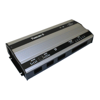
Universal Controller-
ST Coldroom
ZA-10068-EET
E N N N N E
E N N N E
Alarm / Remote
RL5
R
e
m
o
t
e
/
A
l
a
r
m
S
a
t
u
r
a
t
e
d
g
a
s
v
a
l
v
e
/
D
e
f
r
o
s
t
h
e
a
t
e
r
/
D
r
i
p
p
a
n
h
e
a
t
e
r
E
l
e
c
t
r
o
n
i
c
e
x
p
a
n
s
i
o
n
v
a
l
v
e
S
u
c
t
i
o
n
l
i
n
e
v
a
l
v
e
Solenoids
RL1
RL3
RL2
RL4
Fans
Not used
Fans
L
L Line
N Neutral
E Earth
F3
F2
F4
F1
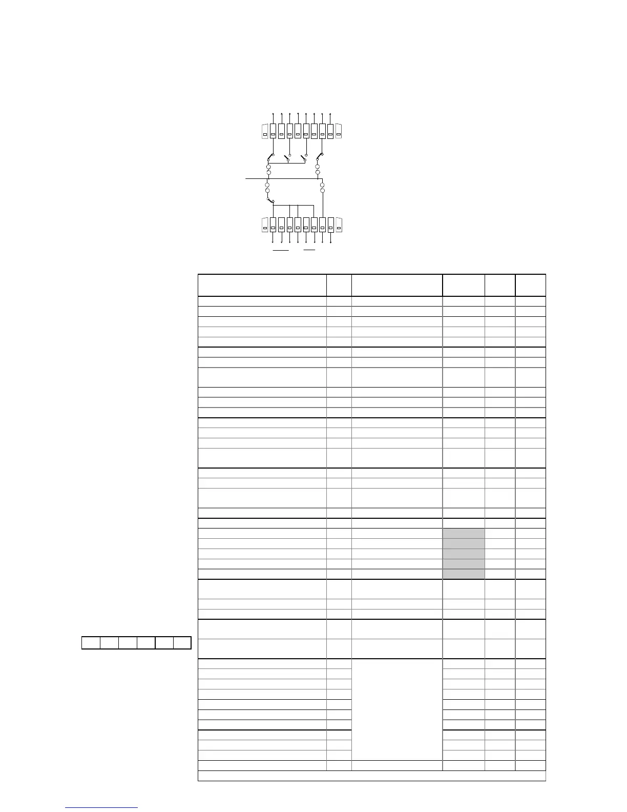
Output Connections (Fig. 3)
Top
Bottom
Output Connections (Fig. 3):
The diagram on the left shows the output
connections to the EEV and suction line valves,
SGV, defrost heater, drip pan heater, remote,
and alarm. The connection to the EPR valve is
made from the front panel, at the two-pin
connector labelled ‘EPR valve’.
A special cable is provided for the network
connection. Neighbouring controllers can be
linked together to form a network by connecting
 Loading...