Commissioning:
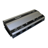
1. Check all electrical connections (Fig. 2).
2. Make sure that the controller software is EET.
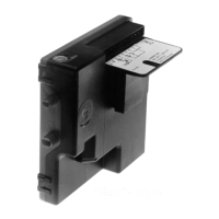
3. Check / Set Bit Switches (Fig. 1).
4. Switch the controller ON.
5. Connect Set-up Unit to DIN Box Display or
controller (Fig. 2).
6. Check / Set operating parameters - see list
7. Save values - if changed
8. Log the controller on to the network then verify
settings on Genus InTouch panel, Set-up Unit
or DIN Box Display.
Fault Finding:
Set-up Unit does not reach the first
screen.
• If the red LED beside the display connector is
ON, then the controller is faulty.
You cannot log the controller on to the
network.
• There may be a controller with the same name,
already logged on the network.
• There may be a maximum 32 controllers
already on the network segment.
• Check on the InTouch panel, P.C. or
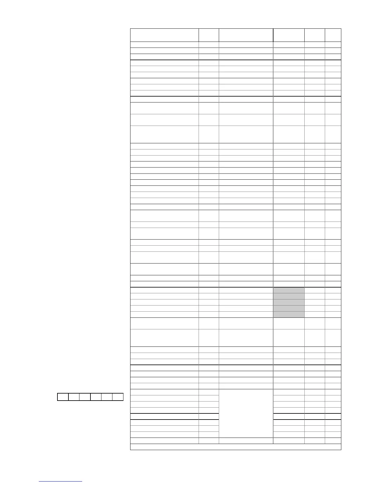
Parameter DIN Range/Units Default
HT(LT)
Dsgn Act.
Red Cycle Temperature 0 1 to 7 / °C 4 (-22)
Red OT Alarm Temp. 2 7 to 10 / °C 8 (-15)
Red UT Alarm Temp. 1 -3 to 4 / °C 2 (-30)
Yellow Cycle Temperature 3 1 to 7 / °C 1 (-22)
Yellow OT Alarm Temp. 5 7 to 10 / °C 5 (-15)
Yellow UT Alarm Temp. 4 -3 to 4 / °C -1 (-30)
White Cycle Temperature 6 1 to 7 / °C 8 (-22)
White OT Alarm Temp. 8 7 to 10 / °C 12 (-15)
White UT Alarm Temp. 7 -3 to 4 / °C 4 (-30)
Differential Below 9 0 to 30 / °C 1.5 (2)
Case Type: 0=Red ; 1=Yellow
; 2=White
10 0 to 2 0
Alarm Delay 00:00 to 99:00/Min:Sec 05:00
(10:00)
Log Probe Type: 0=Off ;
1=Product ; 2=Alarm ;
3=Prod./Alarm
12 0 to 3 0
Red Log OT Alarm 14 8 to 10 / °C 8(-15)
Red Log UT Alarm 13 -1 to 4 / °C 2(-25)
Yellow Log OT Alarm 16 5 to 7 / °C 5(-15)
Yellow Log UT Alarm 15 -2 to 1 / °C 0(-25)
White Log OT Alarm 18 12 to 14 / °C 12(-15)
White Log UT Alarm 17 3 to 7 / °C 4(-25)
Air On / Off Weight 11 0 to 100 / % 50
Defrost Start 19 00:00 to 23:59/Hrs:Mins 01:00
Number of Defrosts per Day 20 0 to 8 6
No Defrost Time 21 0 to 25 / Hrs. 7
Gas Defrost Detect 22 0 to 30 / °C 18
Defrost Terminate
Temperature
23 6 to 14 / °C 10 (14)
Defrost Minimum Time 24 00:00 to 99:00/Min:Sec 05:00
Defrost Maximum Time 25 00:00 to 99:00/Min:Sec 24:00
(25:00)
Drain Down Time 26 00:00 to 20:00/Min:Sec 01:30
Defrost Recovery Time 27 00:00 to 99:00/Min:Sec 30:00
Defrost Type: 0=Elect.;
1= 2Gas ; 2= 3Gas
28 0 to 2 0
Defrost Mode: 0=Local ;
1=Remote
29 0 to 1 0
Defrost Hold: 0=Off ; 1=On 30 0 to 1 0
Fans in Defrost: 0=Off ; 1=On 31 0 to 1 1
Hour 32 0 to 23
Minute 33 0 to 59
Day 34 0 to 31
Month 35 0 to 12
Year 36 0 to 99
BST / GMT Select: 0=Auto ;
1=Man.Off ; 2=Man.On
37 0 to 2 0
Lights / Blind: 0=Local ;
1=Remote ; 2=Man.Off ;
3=Man.On
38 0 to 3 0
Sunday (Blinds) Up / Down 39/40 00:00 to 23:59/Hrs:Mins 08:00/20:00
Monday Up / Down 41/42 00:00 to 23:59/Hrs:Mins 08:00/20:00
Tuesday Up / Down 43/44 00:00 to 23:59/Hrs:Mins 08:00/20:00
Wednesday Up / Down 45/46 00:00 to 23:59/Hrs:Mins 08:00/20:00
Thursday Up / Down 47/48 00:00 to 23:59/Hrs:Mins 08:00/20:00
Friday Up / Down 49/50 00:00 to 23:59/Hrs:Mins 08:00/20:00
Saturday Up / Down 51/52 00:00 to 23:59/Hrs:Mins 08:00/20:00
Superheat reference 53 8.0 (6.0)
Proportional Gain 54 2.0
Integral Gain 55 Do not change the 2.0
Integral Time 56 value of these 03:00
EEV Size 57 parameters 1.0
Temp. Proportional Gain 58 1.5
Temp. Integral Gain 59 0.7
Temp. Integral Time 60 10:00
Manual Defrost: 0=Off ; 1=On 99 0 to 1 0
Display Alarm Messages:
AL Temperature alarm
Ft Probes 1 and 2 are faulty
LA Log probe alarm
Pn probe ‘n’ faulty or not connected
(Where ‘n’ = probe number)
EE EEPROM fault
rr Internal program fault
En Plant fault (‘n’ = number)
Store:..................................................
Controller
Name:
Designer:.............................................
Date:...................................................
Engineer:.............................................
Date:...................................................
Comments:
Universal Controller - 3 Range
ZA-10065-EET
Issue a : 14/5/97
 Loading...