Universal Controller - EET
3 Range
ZA-10065-EET
Issue a : 14/5/97
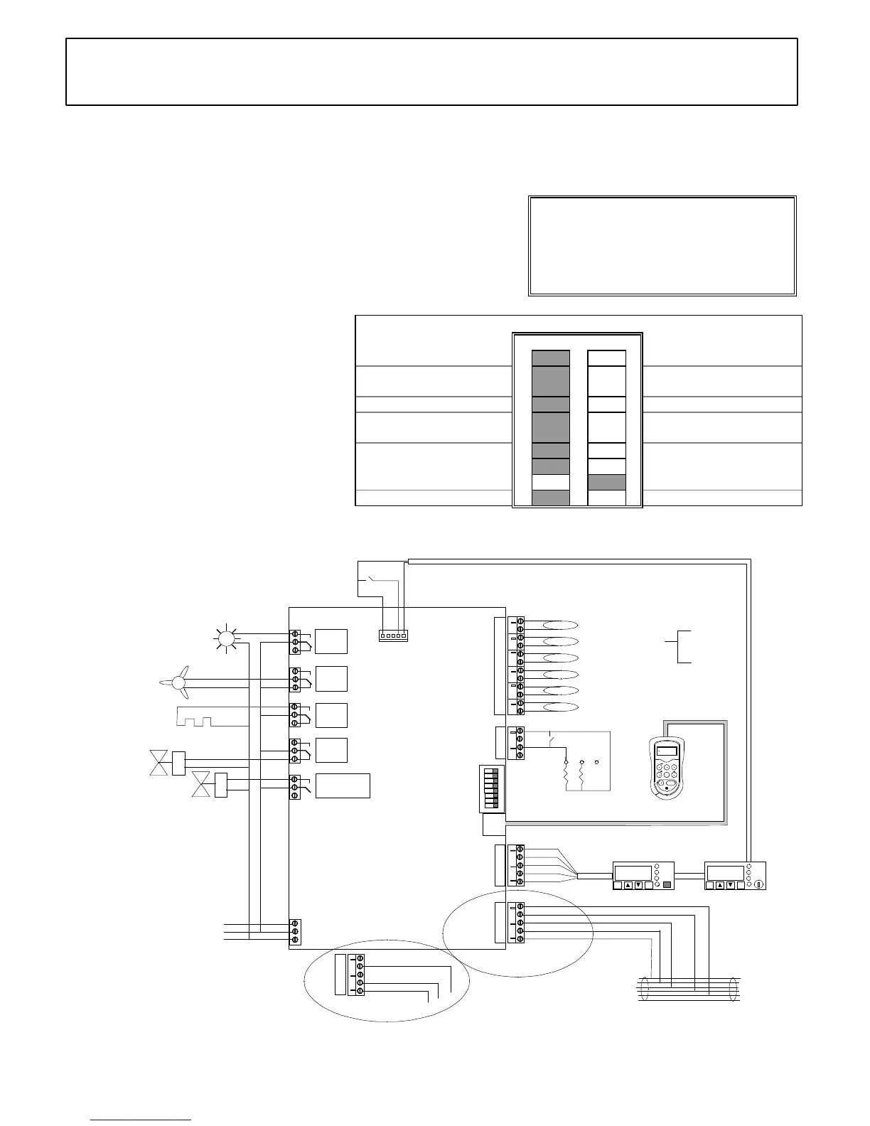
Bit Switch Settings (Fig. 1) : (Shaded area = Switch Position)
Off On
Genus network 1 Alternative network
Elm Probes *
controller part no. 190887
2 PT 1000 Probes **
controller part no. 191126
Relay 5 switches lights 3 Relay 5 Switches Alarm
DIN Display Buttons
Active
4 DIN Display Buttons
Inactive
5
3 Range case option 6
7
Warning !
Before you work on this equipment, isolate the
electrical supply and also the live feed to any
incoming signals. Remember that live signals
may be derived from more than one source.
Relay
1
Relay
2
Relay
3
Relay
4
Relay
5
Note: This simplified wiring diagram omits circuit protection
ON
1
2
3
4
5
6
7
8
(P6) Logging
(P4) Evaporator out
(P3) Evaporator in
(P2) Air off
(P1) Air on
Temperature Probes -
Bit switches
+
OPTIONS EXEC UTE
PAGE
PAGE HOME
SELECT
Setup
Unit
Previous
controller
Next
controller
Genus or alternative
Network cable
-1.5
Ent Esc
Alarm
Network
Defrost
Defrost
Fans
only
Case
off
Normal
N
L
E
Mains
Supply
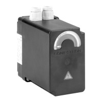
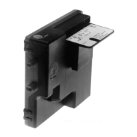
DIN Box Display
Fans wired to Relay 4
N/C contact if bit switch
4 is OFF, or to N/O
contact if bit
switch 4 is ON
Defrost heater
Suction line
valve
Electronic expansion valve
Setup unit extension cable
screen
red
white
black
green
blue
green
yellow
white
red
CN7
CN8
P2
P1
CN9
CN10
CN11
CN12
CN13
CN14
CN15
CN5
CN6
CN4
CN3
CN2
CN1
EET
Controller on a
Genus Network
screen
white
black
CN7
Controller on a
Woodley Network
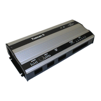
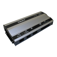
Controller
(Fig. 2)
Position of probes should be in accordance
with case manufacturers instructions
10k
5k
If gas defrost is
required, connect
N/C S.G.V. to
Relay 3 N/C contact
Case lights /
blinds
Alarm wired to Relay 5 N/C
contact if bit switch 3 is ON
(P5) Defrost terminate
not required if
'Fans in Defrost'
is set to ON
-1.5
Ent
Esc
Alarm
Network
Defrost
DIN Box Display
with Keyswitch
OR
white
green
Plant fault
Product Part No:
• Universal Controller * with Elm probes: 190887
•
Universal Controller ** with PT 1000 probes:
191126
Features:
• Controls and monitors HT and LT 3 Range case
• Features a Solid State Relay, which controls an ‘Electronic
Expansion Valve’, for improved temperature control
• Genus or alternative network compatible
•
Associated Documents:
∗ Datasheet: ZD 10070-EET
∗ DIN Box Display: ZF 0920-DIN
∗ Set-up Unit: ZF 0795-DAD
∗ Using Probe Clips: ZG 56003
∗ Health and Safety: ZG 1056
Please Note:
The features and specifications contained in this
Installation Guide may change without notice.
Elm Ltd. shall not be liable for errors or for incidental or
consequential damages in connection with the
furnishing, performance or use of this product or
document.
 Loading...