CLASS 320 METER
23 62-0397-02
6.7 RS-485 Wiring (continued)
6.7.1 RS-485 Bias Resistors
When interfacing the Class 320 meter to certain RS-485 communication equipment, it
may be necessary to add bias resistance to the circuit. If this is required, there is a 2-
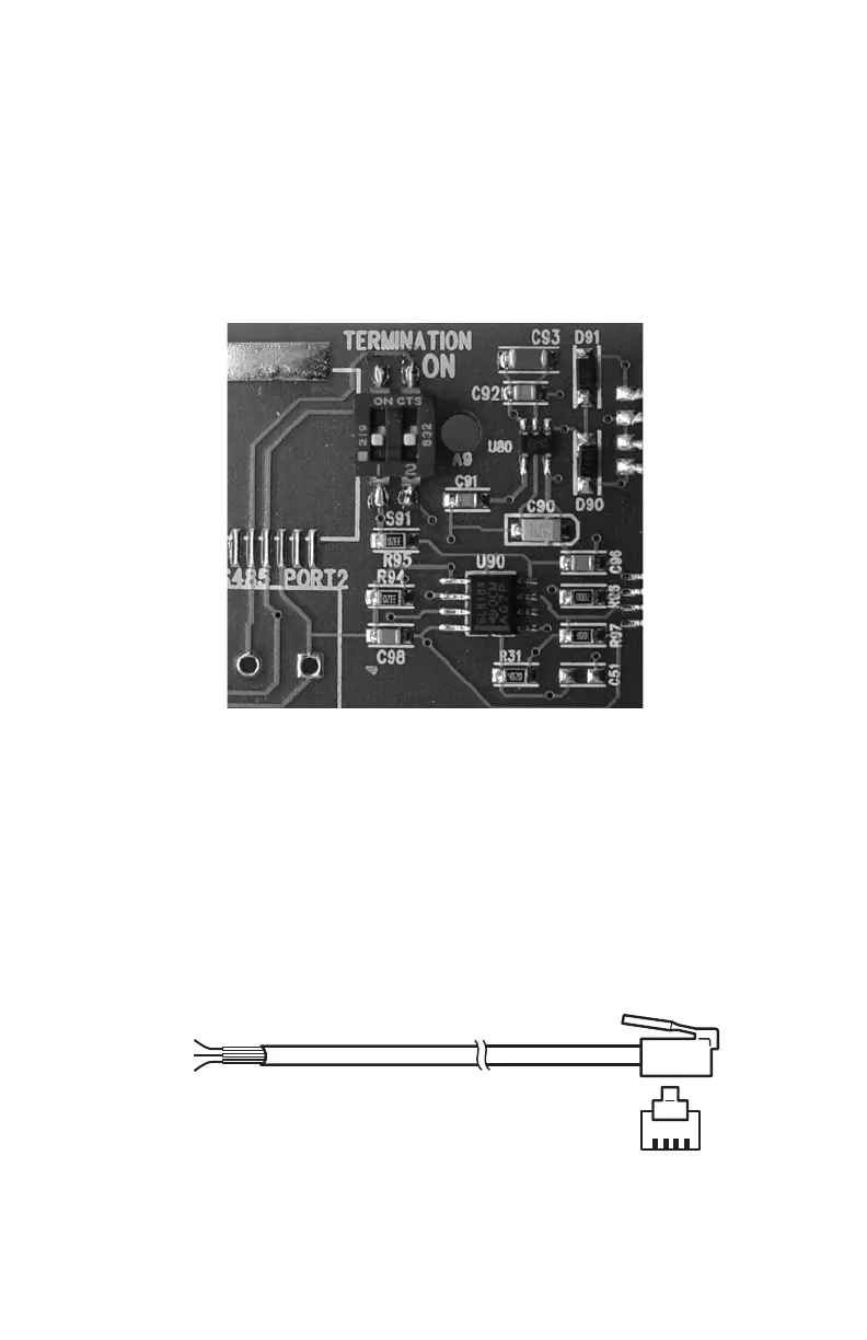
position DIP switch on the meter’s door mounted (display) circuit board. With both
positions in the “ON” position, bias resistance is added to the RS-485 circuit. When
both positions are in the “OFF” position, no bias is added to the RS-485 circuit.
Fig. 13. Bias Resistors DIP Switch.
After performing these steps, all of the meters will be connected in a daisy chain
configuration. This network of meters can then be connected to the RS-485 network
and communication can be established.
Local Computer
A local computer installed in the building can communicate with the RS-485 network
utilizing Honeywell’s RS-232 conversion key. The RS-232 key is connected to the RS-
485 terminals in the closest meter using a cable with an RJ-11 plug terminating the
end that is plugged into the key and is open wiring on the other end for attachment to
the meter’s 3-screw RS-485 terminal block.
Fig. 14. RS-485 Wiring.
RJ−11
PLUG
FRONT VIEW
M33196
1 - NC
2 - GND
3 - HIGH
4 - LOW
GND (GREEN)
HIGH (BLACK)
LOW (RED)
2 3 4
 Loading...


