CLASS 320 METER
5 62-0397-02
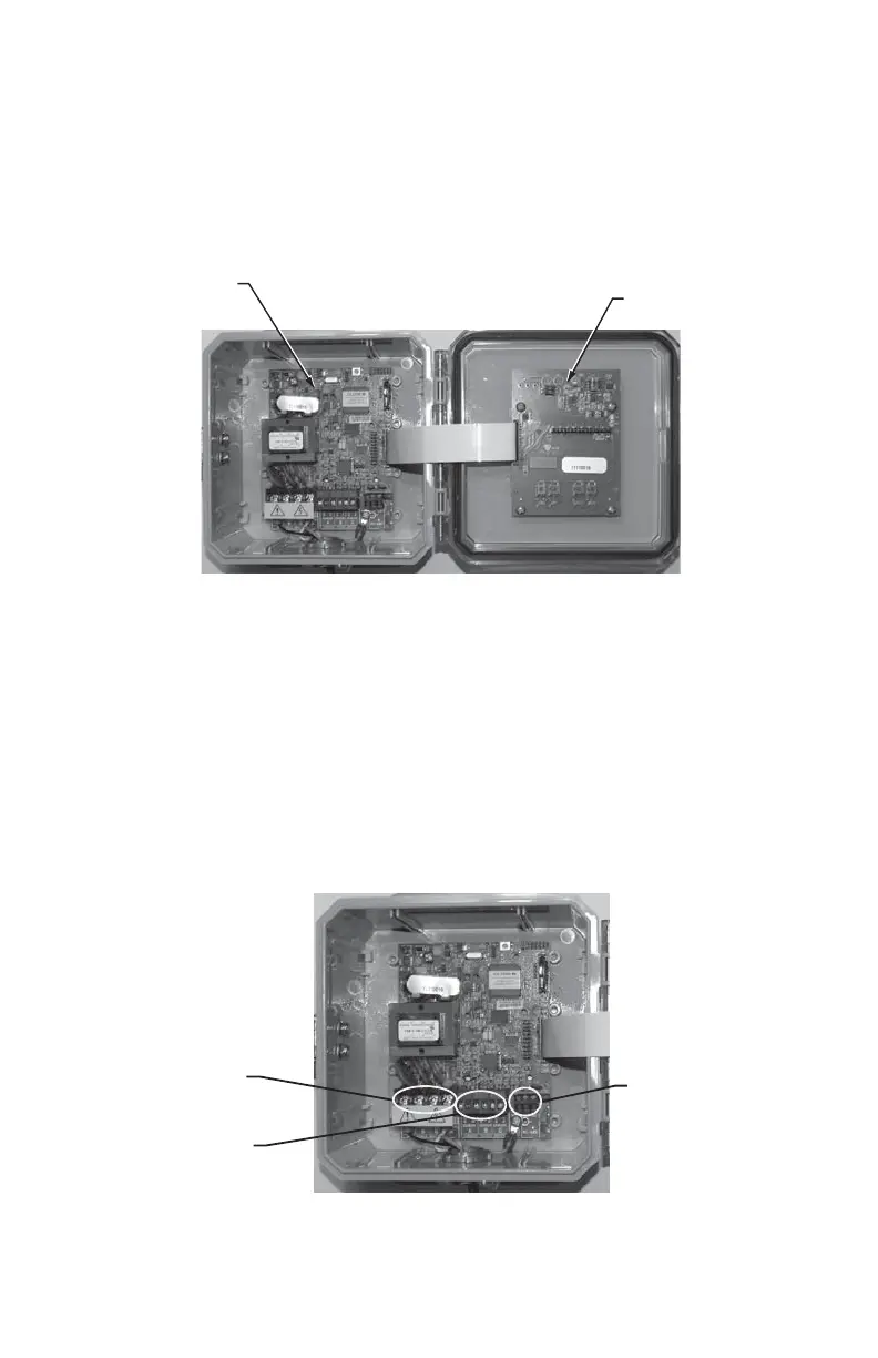
2.0 INTERNAL ELECTRONIC ASSEMBLIES
The units are comprised of two major subassembly boards, the main power board and
the display board. Both circuit boards are mounted inside a UL Type 1 (steel) or Type
4X (rain tight) enclosure.
Fig. 1. Internal Electronic Assemblies.
2.1 Main Power Board
Connections to this board include the MAIN Power Input and current sensors.The
MAIN Power Input terminals are positions one through four on the four position screw
terminal block, TB1. These terminals are covered with a protective shield for safety
purposes. The current sensor assemblies interface to TB2, TB3 and TB4. Each
terminal block corresponds to an input voltage phase; care must be exercised to
ensure that each current sensor is connected to the correct terminal block. One three
terminal screw connector is provided for RS-485 communications.
Fig. 2. Main Power Board Connections.
M33307
MAIN
POWER
BOARD
DISPLAY
BOARD
M33308
RS-485
MAIN
POWER
INPUT
CURRENT
SENSOR
INPUT
 Loading...


