EKZ000300C Page : 6/24
Installer instructions / Manuel installateur - Domonial CMI 800++ 11/2005
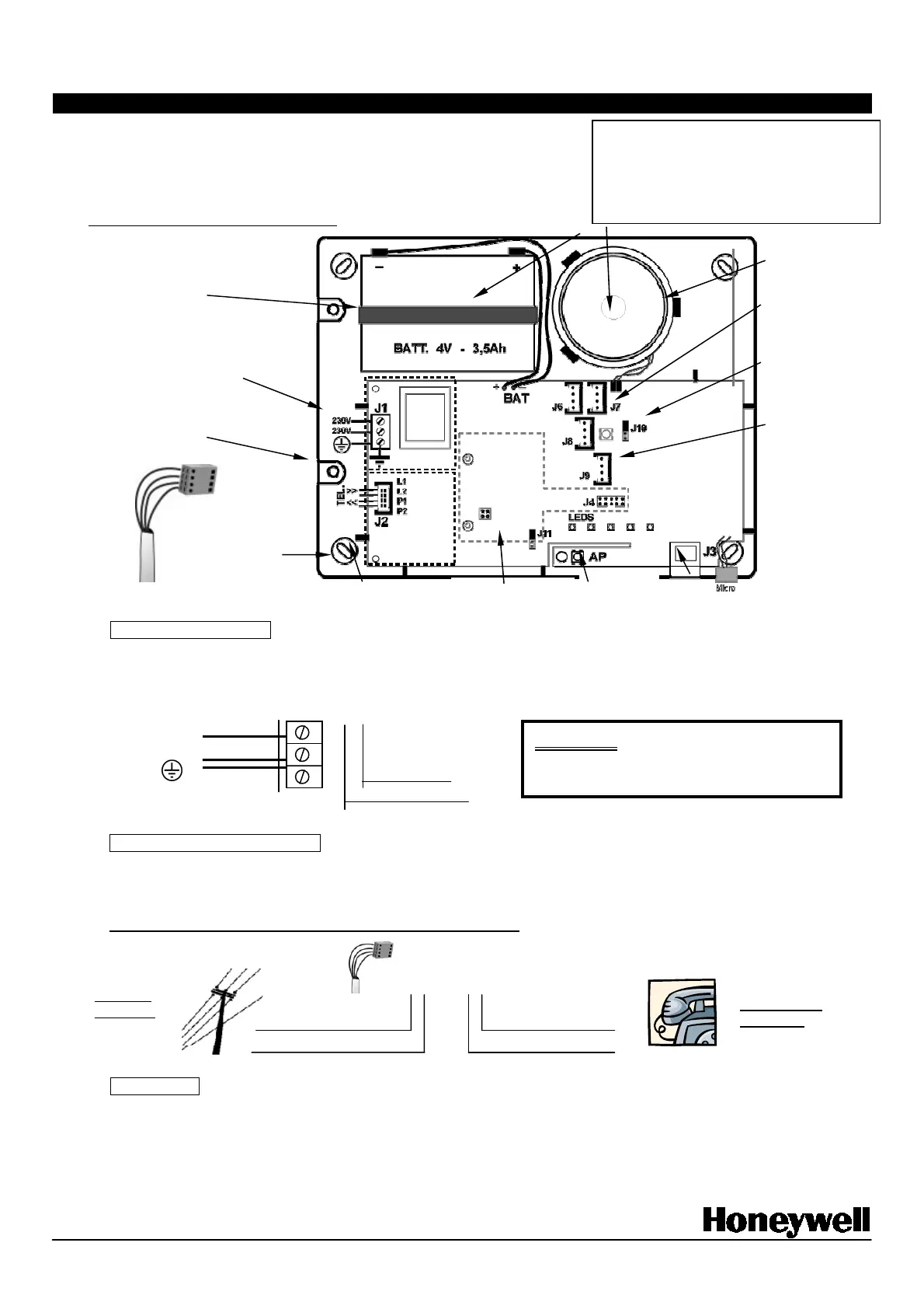
2-2 Securing the control panel CRT/CRI800++ and connections
The control panel has 4 securing points.
The base can be used as a template for holes marking.
Detach the various cut outs before securing the panel and use to plug holes as required.
Do not use the base as a drilling template.
Mains: (Terminal block J1)
The control panel is supplied from the mains, 230V with earth. A built-in transformer ensures supply to the control panel and battery
charging. The mains is protected by a fuse integrated into the circuit board. It protects the electrical system and cannot be removed.
A fused switch /spur (depending on country) must be used for connecting the CRT/CRI800++ to the mains.
Telephone line (Terminal block: J2)
Connect the telephone line using the "Stocko" connector (included). Terminals "L1, L2" and "P1, P2" are marked and correspond to
telephone line input and return to set respectively. (If you’re using an ADSL line, please visit our web site for information about filter)
The control panel must be connected so as to override any other call.
Serial port (J3)
A serial port is available to connect the programming tool or a personal computer (with optional cord) via an RJ45 connector.
Cable reference: CAB800PC (or CAB800PALM for the connection with a PDA). Specific serial cables are sold separately.
Wire passage
Velcro straps for
securing battery
230V~
230V~
J1
Transformer
Warning :
This Class I system must be earthed
Pre-cut caps for :
- cover wires passage (under the battery)
- programming connector (under the
sounder)
(Can be supplied as kit on some models.)
MAINS + EARTH
connection (1.5mm
2
minimum)
Connection to Client's phone line
Built-in Speaker
Connectors for
wired extensions
Audio devices
setting J10/J11
(internal/external)
Connectors for
XM10 transmitter
4 holes for 3.5
screws
Tamper
Programming tool
connector
4 pin Stocko
connector
PNV
(*)
Warning
230V~
SELV
(*)
*
PNV : Phone Network
Voltage
SELV : Security Elecrtical
Incoming
J2 connector :
Transmitter terminal block:
Line Return to Phone
Telephone set
connection
Optional GSM
module
 Loading...