Basics for installing the device in a pipe
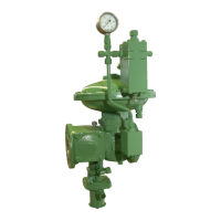
HON 380 gas pressure regulator with HON 673/674 controller 24
4.2 Meter run characteristics
The following recommendations are based on the measuring line connection
conditions set forth in standards (DIN) EN 334 and (DIN) EN 14382. The com-
pany operating the system is the sole party responsible for the meter run working
properly.
A pipe area with a steady flow pattern must be selected for the sensing point.
There must not be any components that disturb the flow directly upstream
and downstream of the sensing point, e.g., orifice plates, expanders, bends,
junctions, shut-off devices, etc.
The flow rate at the sensing point should not exceed approx. 25 m/s, de-
pending on the system conditions.
In the case of specific system circuits (such as gas regulating lines for gas
engines) and in the case of gas burners, flow rates higher than 25 m/s may
be allowed following consultation with the manufacturer.
Within a low-pressure range of up to approx. 250 mbar, a maximum flow rate
of approx. 15 to 20 m/s is recommended at the sensing point. On a case-by-
case basis, and following consultation with the manufacturer, even lower
flow rates may be allowed.
Depending on the specific system design, the L
uR
lengths of the undisturbed
pipes upstream of the sensing point must be (2.5 to 5) x DN of the pipe, with the
specifics depending on the gas pressure regulator model and whether or not
there is a pipe expander downstream:
If … and... then...
A gas pressure regulator
with an expander that is part
of the device is used
The nominal size of the pipe
is equal to the outlet-side
nominal size of the gas
pressure regulator
L
uR
min. 2.5 x DN
The nominal size of the pipe
is the next larger standard
nominal size
L
uR
min. 3 x DN
The nominal size of the pipe
is two standard nominal size
increments larger
L
uR
min. 4 x DN
The nominal size of the pipe
is more than two standard
nominal size increments
larger
L
uR
min. 5 x DN
A gas pressure regulator
with the same outlet nomi-
nal size as the inlet nominal
size is used
The nominal size of the pipe
is the next larger standard
nominal size
L
uR
min. 4 x DN
The nominal size of the pipe
is two standard nominal size
increments larger
L
uR
min. 5 x DN
basis
meter run
sensing point
 Loading...