Maintenance
HON 380 gas pressure regulator with HON 673/674 controller 41
8.3 Starting maintenance
Risk of serious injury posed by pressurized components moving in an uncon-
trolled manner when handled improperly.
If not handled properly or in the event of a defect, gas can escape from pressur-
ized components under high pressure and cause serious injuries and even death.
Before you start working on these components:
Close all connections leading to the gas-carrying line.
Establish a depressurized status. Residual amounts of energy must be depres-
surized as well.
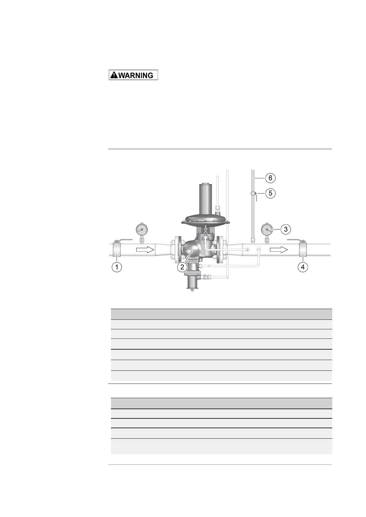
Schematic diagram using the RE1 DN50 and HON 673 as a reference:
The numbers have the following meaning:
No. Meaning
1 Inlet stop valve armature
2 Gas pressure regulator
3 Pressure gauge
4 Outlet stop valve armature
5 Valve for blowdown line
6 Blowdown line
Proceed as follows:
Step Description
1 Close the outlet stop valve armature (4).
2 Close the inlet stop valve armature (1).
3 Depressurize the gas pressure regulator.
4 Open the ball valve (5) in the blowdown line (6) to discharge the pressure be-
tween the inlet and the outlet valves.
Establishing the de-
pressurized status
 Loading...