10
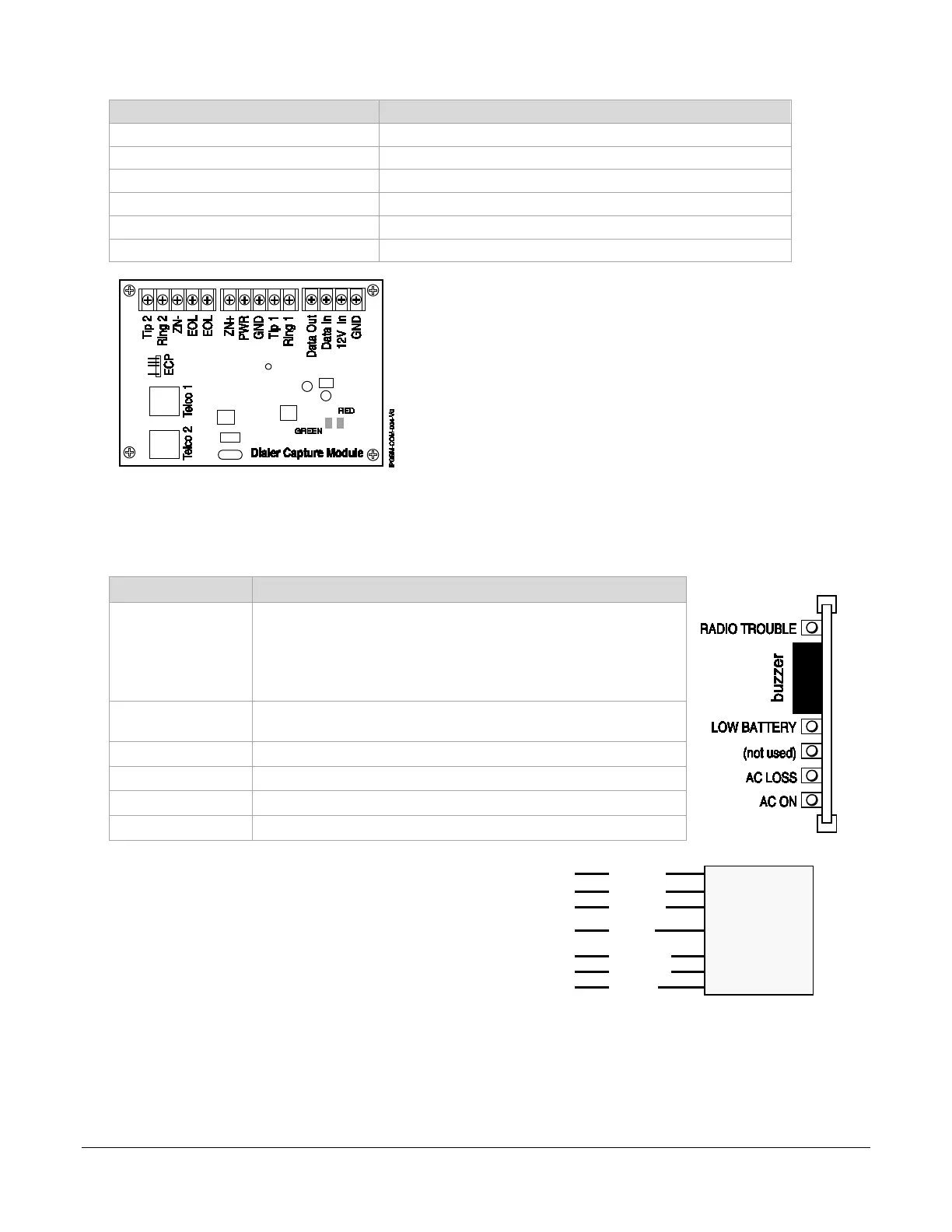
Dialer Capture Module Information
LED Indicator STATUS
RED – Steady ON Messages exist in buffer.
RED – Flashing No messages to be sent. Waiting for messages.
GREEN – Steady ON Normal Indication.
GREEN – Blinks every 2 sec. PowerBoost1 communication problem.
GREEN – Blinks twice every sec. Connection with the Communicator is lost.
GREEN – Blinks 10 times every sec. PowerBoost1 and Communicator connections are lost.
LED Display Information
Status LED Indicator
RADIO TROUBLE Yellow – ON when radio trouble is present.
• Both IP and Cell communication paths are lost.
• Communicator radio is not registered.
• Old Alarm Time has been exceeded. (Message has not been
delivered within the fixed 10-minute window.)
Buzzer – Upon loss of AC power, this will beep once every 10 sec-
onds.
Yellow – ON when battery is low (<11.5VDC).
Yellow – (not used)
AC LOSS Yellow – ON when no AC is present (< 90VAC).
AC ON Green – ON when AC is present.
NOTE: If a wire pulled out of the LED Board Connector
refer to the diagram on right and reinsert wire, ensuring
the connector pin is locked in.
NOTE: Telco ports 1 (primary dialer) and
2 (secondary dialer) may be used instead
of the terminal board.
Whichever connection method is used,
both Telco paths must be connected to
the Fire Panel.
NC
NC
LED Board
Connector
Wires
Violet
Black
White
Red
Brown
Yellow
Gray
 Loading...