Section 2: Mounting and Wiring
9
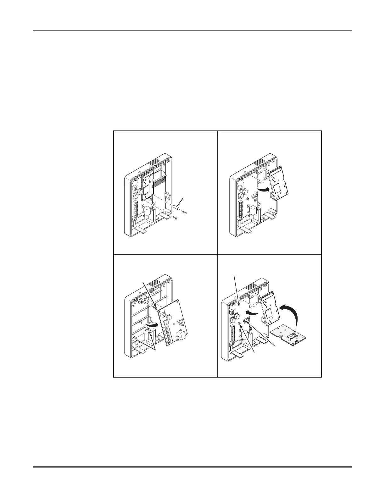
Mounting Procedure, LTE-I (with rear tamper switch)
For Canadian installations where the rear tamper switch is used, this procedure requires the
removal of the printed circuit boards and installation of the tamper screw.
1. Remove the two mounting screws, and standoff from the daughter card, as shown in Step A
below.
NOTE: Do not apply tension to the internal antenna fastened to the back cover or to the
cable that connects this antenna to the daughter card.
2. Remove the daughter card by pivoting upward, as shown in Step B below.
3. Remove the lower printed circuit board by pushing down on the lower tabs and pivoting the
board upward, as shown in Step C below.
INSTALL
TAMPER
SCREW
STEP A STEP B
STEP C STEP D
PRESS DOWN TABS
AND PIVOT UP
SCREW
POSTS
(2)
CONNECTOR
REMOVE
2 SCREWS
AND
STANDOFF
SLIDE CARD BETWEEN
TABS AND PIVOT DOWN
SEAT SMALL CARD
AND FASTEN WITH
2 SCREWS AND
STANDOFF
4. Locate the case back over selected mounting position such that the opening in the case back
is aligned with the wire/cable opening on the mounting surface.
5. Pass the wires/cable through the opening in the case back, or route through the removable
knockouts located on the back cover.
6. Secure the case back to the mounting surface using four screws (supplied).
7. Install the tamper screw (provided), as shown in Step C above.
8. Replace lower printed circuit board and then daughter card, as shown in Step D above. Be
sure to engage receptacle pins by pushing in before securing the daughter card with
mounting screws.

 Loading...