AA-series Audio Amplifiers Manual for DVC-AO Applications — P/N 52526:B 8/13/2019 13
AA-100/AA-120 Installation Amplifying Audio Messages
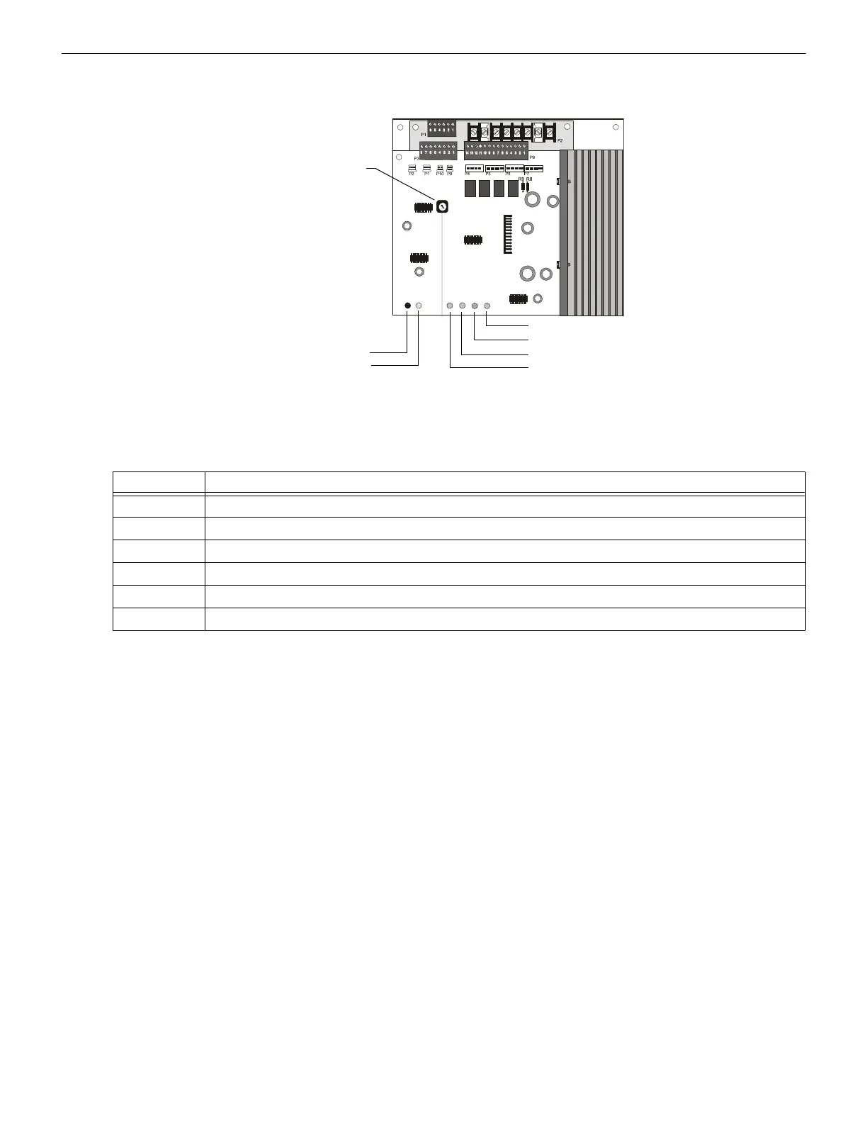
3.4.1 Circuit Board Layout
Layout of the AA-30 circuit board and identification of its operating components:
3.4.2 LED Conditions
Conditions that cause each AA-30 System Status Indicator LED to light:
3.5 AA-100/AA-120 Installation
3.5.1 Installing an AA-100 or AA-120
The AA-100 or AA-120 mounts directly to the cabinet backbox. The following steps apply to the installation of an Audio Amplifier:
1. Mount the unit into the system cabinet.
2. Connect primary (AC) and secondary (24 VDC battery) power source to the unit.
3. Provide an external device (such as a CHG-120) for charging the batteries.
4. Adjust the Audio Gain Level. See page 16.
5. Select a Backup Tone. See page 16.
3.5.2 Mounting an AA-100 or AA-120
Mount an AA-100 or AA-120 directly to the backbox by following these steps and referring to the figure below:
1. Mount the AA-100 or AA-120 onto the PEM studs on the cabinet backbox (in the same way as the CHS-4 and CHS-4L chassis) as
shown below.
Audio Gain
Rotary Switch
Normal Level LED
Incorrect Level LED
Speaker Trouble LED
Amplifier Trouble LED
Battery Trouble LED
Brownout LED
AA-30.wmf
Figure 3.6 AA-30 LED and Switch Locations
LED Lights when
normal level The audio amplifier is adjusted properly and operating correctly during normal (non-alarm) conditions.
incorrect level Low-level audio input is missing, out of range, or the audio gain is out of adjustment.
speaker trouble An open circuit condition occurs in the four-wire, high-level output.
amplifier trouble A loss of the low-level audio input signal, or an amplifier failure.
battery trouble The battery voltage is below a sufficient level.
brownout The AC power source is below a sufficient level. During a complete loss of AC power, no LEDs will light on the AA-30.
Table 3.1 AA-30 LED Functions
 Loading...