18 AA-series Audio Amplifiers Manual for DVC-AO Applications — P/N 52526:B 8/13/2019
Amplifying Audio Messages Wiring Multiple Audio Amplifiers
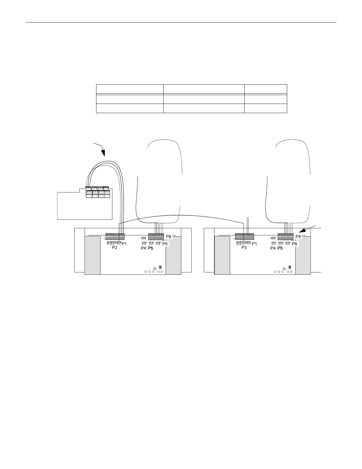
3.8.2 Two Primary AA-100/AA-120s Without Backup
Figure 3.13 and Figure 3.14 show the use of two audio amplifiers without backup and Table 3.5 lists the wiring components used.
• The speaker circuits on the first audio amplifier share 100/120 watts from that audio amplifier; the speaker circuits on the second
audio amplifier share 100/120 watts from that audio amplifier.
• To use high-level audio (25 Vrms output) with four-wire supervision, cut resistor R100 on the AA-120 or AA-120 (Figure 3.10).
• This wiring diagram applies to AA-100 and AA-120 audio amplifiers. Connections to plugs P1, P2, P4, P5, P6, P9, and P10 are
identical.
Typical wiring of two primary AA-120 audio amplifiers without using a backup amplifier. This option shows how to connect to speaker
circuit control modules at a distance, using twisted-pair wire (18 AWG recommended):
Item Supplied with Part Number
Low-level audio cable AA-100, and AA-120 75110
25-volt audio cable AA-100, and AA-120 75109
Table 3.5 Wiring Inventory
AA-120-nobackupDVCAO.wmf
DVC-AO Outputs
1, 2, 3, or 4
(See DVC Manual for
details)
2nd AA-120
25V High-level Output
to Speaker Circuit
Control Modules
(e.g. XP6-C, FCM-1)
25V High-level Output
to Speaker Circuit
Control Modules
(e.g. XP6-C, FCM-1)
Optional
4-Wire
Supervised
Return
(High-Level)
Cable
75110
Optional
Class A
Audio
Return*
(Low-Level)
Shield
Unamplified
low-level audio
(Twisted-pair,
14-18 AWG)
1st AA-120
Optional
4-Wire
Supervised
Return
(High-Level)
Notes: Cables must enter from top of the plug.
*Note: If not using Class A low-level audio return, an R-470 resistor assembly may be installed across P3, pins 4 and 5 of the last
directly connected device on the low-level audio riser; this may help to calibrate the audio amplifier.
Figure 3.13 Wiring Two AA-120’s Without a Backup Amplifier
 Loading...