14 AA-series Audio Amplifiers Manual for DVC-AO Applications — P/N 52526:B 8/13/2019
Amplifying Audio Messages AA-100/AA-120 Installation
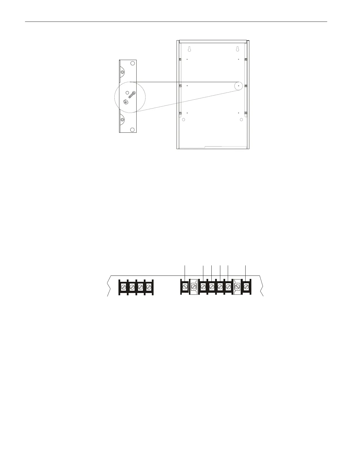
2. Install the two #8 nuts and lock washers (Figure 3.7) onto the PEM studs and tighten until secure.
3.5.3 Connecting an AA-100 or AA-120
Figure 3.8 and Figure 3.9 show terminal connections to an AA-100/AA-120.
• Low-level audio input and high-level audio output “P” connectors are primarily for in-cabinet applications where the wiring to or
from the amplifier remains in the cabinet. For multiple-cabinet applications hard-wire the system using terminal blocks P3 & P8.
When more than one cabinet is required, cabinets must be mounted adjacent to each other and all interconnecting wiring must be
installed in conduit.
• To use high-level audio (25 Vrms output) with four-wire supervision, cut resistor R100 as shown in Figure 3.10. Note: In the AA-
120, this option is only required when output wiring leaves the cabinet.
• If the amplifier is being used in stand-alone mode (no connection to DVC-AO) where the backup high/low or slow whoop tone
generator is being used, resistor R107 (see Figure 3.10) must be cut to prevent the amplifier from generating a trouble condition.
The amplifier will indicate trouble within 90 seconds.
• Some installations require an ACT-1 or ACT-2 Audio Coupling Transformer. See the ACT-1 Installation Document or the ACT-2
Installation Document for further details and installation instructions.
AA120mount.wmf
AA-100/-120
Figure 3.7 Mounting an AA-100 or AA-120
Secondary (DC) Power
Battery
––++
Primary (AC) Power
Earth Hot Neutral Earth
AA120lobrd.wmf
Figure 3.8 AA-100/AA-120 Lower Board Connections (nonpower limited)
 Loading...