RM7897A1002, RM7897C1000 7800 SERIES RELAY MODULES
3 66-1151
Wiring Subbase
WARNING
Electrical Shock Hazard.
Can cause severe injury, death or equipment
damage.
Disconnect the power supply before beginning
installation. More than one disconnect may be
required.
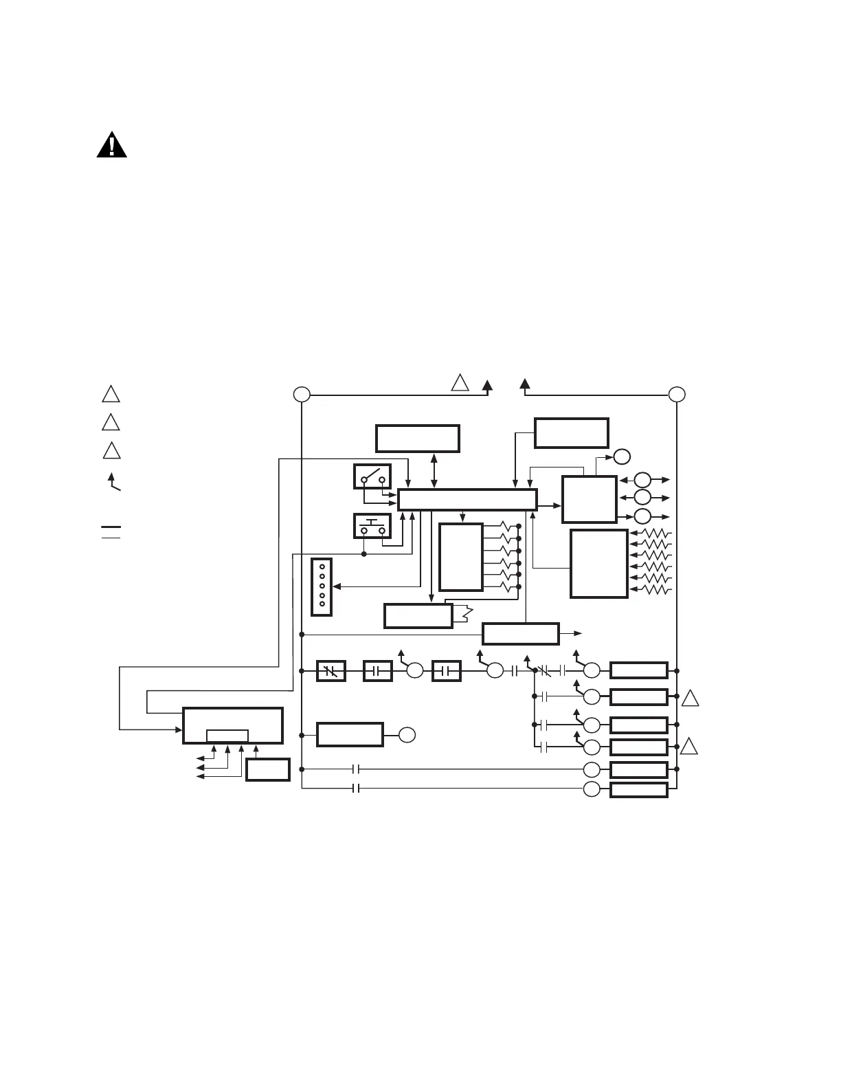
The internal block diagram of the RM7897A,C is shown in Fig.
1.
1. For proper subbase wiring and sequence chart, refer to
Fig. 2 and 3.
2. For remote wiring of the Keyboard Display Module, refer
to the Specifications for the Keyboard Display Module
(65-0288), Network Interface Unit (63-2278), Data
ControlBus™ Module (65-0091) or Extension Cable
Assembly (65-0131).
3. Disconnect the power supply from the main disconnect
before beginning installation to prevent electrical shock
and equipment damage. More than one disconnect can
be required.
4. All wiring must comply with all applicable electrical
codes, ordinances and regulations. Wiring, where
required, must comply with NEC, Class 1 (Line Voltage)
wiring.
5. For recommended wire size and type, see Table 1.
6. For recommended grounding practices, see Table 2.
Fig. 1. Internal block diagram of RM7897A,C (see Fig. 2 and 3 for detailed wiring instructions).
7. Recommended wire routing of leadwires:
a. Do not run high voltage ignition transformer wires
in the same conduit with the flame detector, Data
ControlBus Module™, or Remote Reset Module
wiring.
b. Do not route flame detector, Data ControlBus™
Module, or Remote Reset Module leadwires in
conduit with line voltage circuits.
c. Enclose flame detector leadwires without armor
cable in metal cable or conduit.
d. Follow directions in flame detector, Data
ControlBus™ Module, or Remote Reset Module
Instructions.
8. The KDM is powered from a low voltage, energy limited
source. It can be mounted outside of a control panel if it
is protected from mechanical damage.
NOTE: A 13 Vdc power supply must be used any time more
than one KDM is used.
CONFIGURATION
JUMPERS
MICROCOMPUTER
RESET
PUSHBUTTON
RUN/TEST
SWITCH
STATUS LEDs
PLUG-IN PURGE
TIMER CARD
SAFETY RELAY
CIRCUIT
POWER SUPPLY
OPTIONAL KEYBOARD
DISPLAY MODULE
PLUG-IN
FLAME
AMPLIFIER
RELAY
DRIVE
CIRCUIT
CONTROL
POWER
TEST
JACK
REMOTE
RESET
DDL
DDL
COMMUNICATIONS
INDICATES FEEDBACK SENSING
TO RELAY STATUS FEEDBACK
AND LINE VOLT INPUTS
FIELD WIRING
INTERNAL WIRING
IGNITION
PILOT
MAIN VALVE
1K
RELAY
STATUS
FEEDBACK
AND LINE
VOLTAGE
INPUTS
LIMITS
CONTROLLER
LOCKOUT
INTERLOCK
(INCLUDING
AIRFLOW SWITCH)
1K1 2K1 5K1
FLAME SIGNAL
TEST
PROVIDE DISCONNECT MEANS AND
OVERLOAD PROTECTION AS REQUIRED.
RM7897A-INTERMITTENT PILOT.
RM7897C-INTERRUPTED PILOT.
RM7897A-INTERRUPTED PILOT.
RM7897C-DELAYED MAIN VALVE.
RS485
1
2
3
L1
(HOT)
L2
5
6
7
4K1
2K2
10
8
9
7K
6K
5K
4K
3K
2K
F
G
22
1
BLOWER
6K1
4
ALARM
3K1
3
L2
M22727A
1
2
120 VAC,
50/60 HZ
PREIGNITION
INTERLOCK
20
7K16
21
2
3
3
 Loading...
