RM7897A1002, RM7897C1000 7800 SERIES RELAY MODULES
7 66-1151
STATIC CHECKOUT
After checking all wiring, perform this checkout before
installing the RM7897A,C on the subbase. These tests verify
the Q7800 Wiring Subbase is wired correctly, and the
external controllers, limits, interlocks, actuators, valves,
transformers, motors and other devices are operating
properly.
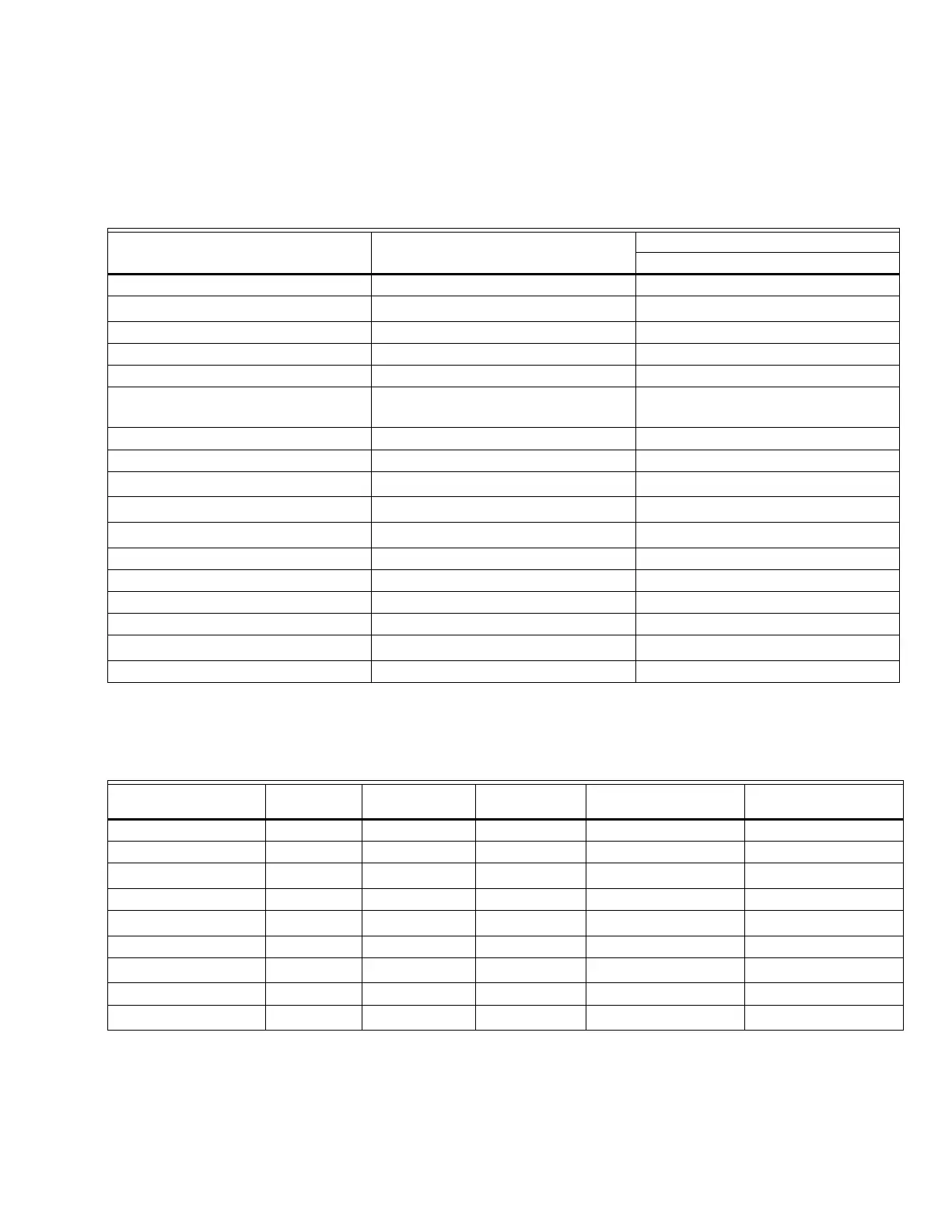
Table 3. Terminal Ratings.
a
See Table 2.
b
2000 VA maximum load connected to RM7897A,C Assembly.
c
See Tables 4 and 5.
Table 4. Combinations for Terminals 8, 9, 10 and 21.
a
RM7897C only, jumper terminals 8 to 9.
Terminal Number Description
Ratings
RM7897A,C
G Flame Sensor Ground —
Earth G
Earth Ground
a
—
L2(N) Line Voltage Common —
3 Alarm 120 Vac, 1A pilot duty.
4 Burner Motor 120 Vac, 9.8A AFL, 58.8 ALR (inrush).
5 Line Voltage Supply (L1) 120 Vac (+10/-15%), 50 or 60 Hz
(±10%).
b
6 Burner Controller and Limits 120 Vac, 1 mA.
7 Lockout Interlock 120 Vac, 8A run, 43A inrush.
8 Pilot Valve/Ignition
120 Vac
c
9 Main Fuel Valve
120 Vac
c
10 Ignition
120 Vac
c
F(11) Flame Sensor 60 to 220 Vac, current limited.
12 to 19 — —
20 PreIgnition Interlock 120 Vac, 1 mA.
21 Interrupted Pilot (RM7897A) 120 Vac
21 2nd Stage Main Valve (RM7897C)
120 Vac
c
22 Shutter 120 Vac, 0.5A
Combination Number Pilot Fuel 8 Main 9 Ignition 10
Delayed Main Valve 21
(RM7897A Only)
Delayed Main Valve 21
(RM7897C Only)
1 C F No Load C No Load
2 B F No Load B No Load
3
F
a
F A F No Load
4 F F A F No Load
5
F
a
FAF F
6 D F A D No Load
7
D
a
DA D D
8 D D A D No Load
9
D
a
No Load A D D
 Loading...
