RM7897A1002, RM7897C1000 7800 SERIES RELAY MODULES
9 66-1151
Mounting Other System Components (Fig. 4)
Refer to the applicable specifications for mounting other
system components.
Setup of Post Purge
An S7800A1142, Keyboard Display Module (KDM), is
required for the setup of the RM7897 Post Purge Timing, and
must be purchased separately.
When the RM7897A,C is installed and powered, “STANDBY”
will be shown on the first line of the display (Fig. 5).
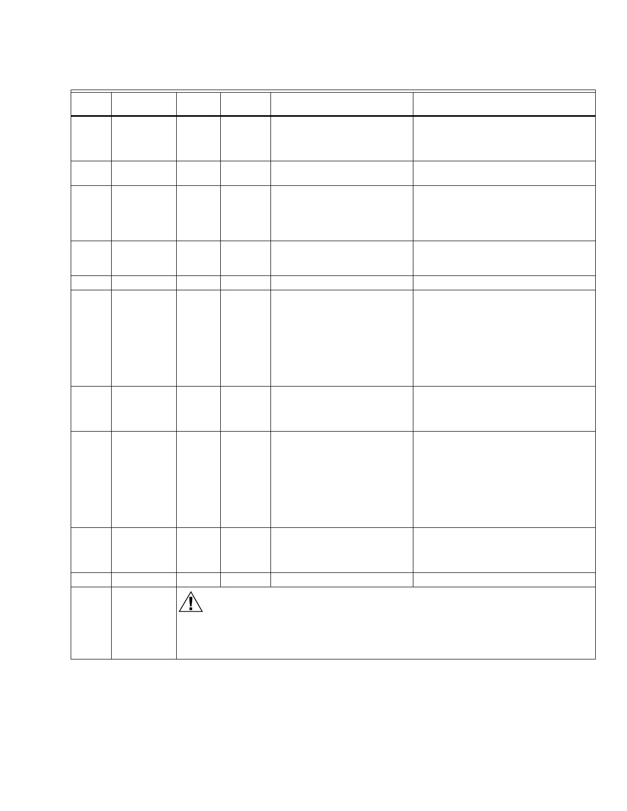
Table 6. Static Checkout.
Test
Number
Relay Module
Model
Test
Jumpers Voltmeter Normal Operation
If Operation is Abnormal,
Check Items Listed Below
1 All None 5-L2 Line voltage at terminal 5. 1. Master switch.
2. Power connected to master switch.
3. Overload protection (fuse, circuit breaker,
etc.) has not opened power line.
2 All None 6-L2 Line voltage at terminal 6. 1. Limits.
2. Burner controller.
3 All 4-5 7-L2 1. Burner motor (fan or blower)
starts.
2. Line voltage at terminal 7
within 10 seconds.
1. Burner motor circuit.
a. Manual switch of burner motor.
b. Burner motor power supply, overload
protection and starter.
c. Burner motor.
4 All 5-10 — 1. Ignition spark (if ignition
transformer is connected to
terminal 10).
1. Watch for spark or listen for buzz.
a. Ignition electrodes are clean.
b. Ignition transformer is okay.
5 All 20-L2 Line voltage at Terminal 20 Preignition Interlocks.
6All 5-8— 1. Ignition spark (if ignition
transformer is connected to
terminal 8).
2. Automatic pilot valve opens
(if connected to terminal
8).
NOTE: Refer to wiring diagram
of system being tested.
1. Watch for spark or listen for buzz.
2. Listen for click or feel head of valve for
activation.
a. Actuator if used.
b. Pilot valve.
7 All 5-9 — Automatic fuel valve(s) open(s). If
using direct spark ignition, check
first stage fuel valve(s) instead of
pilot valve.
Same as test 6. If using direct spark
ignition, check first stage fuel valve(s)
instead of pilot valve.
8a RM7897A 5-21 — 1. Ignition spark (if ignition
connected to terminal
21).
2. Automated Pilot Valve
opens (if connected to
terminal 21).
NOTE: Refer to wiring diagram
of system being tested.
1. Watch for spark or listen for buzz.
2. Listen for click or feel head of valve for
activation.
a. Actuator if used.
b. Pilot valve.
8b RM7897C 5-21 — Automatic second stage main fuel
valve(s) open(s).
1. Listen for and observe operation of
second stage main fuel valve(s) and
actuator(s).
2. Valve(s) and actuator(s).
9 All 5-3 — Alarm (if used) turns on. 1. Alarm.
Final All
CAUTION
Equipment Damage Hazard.
Can cause equipment damage.
After completing these tests, open master switch and remove all test jumpers from subbase
terminals. Also remove bypass jumpers, if used, from low fuel pressure limits.
 Loading...
