RM7898A 7800 SERIES VALVE PROVING PRIMARY RELAY MODULES
19 32-00209—03
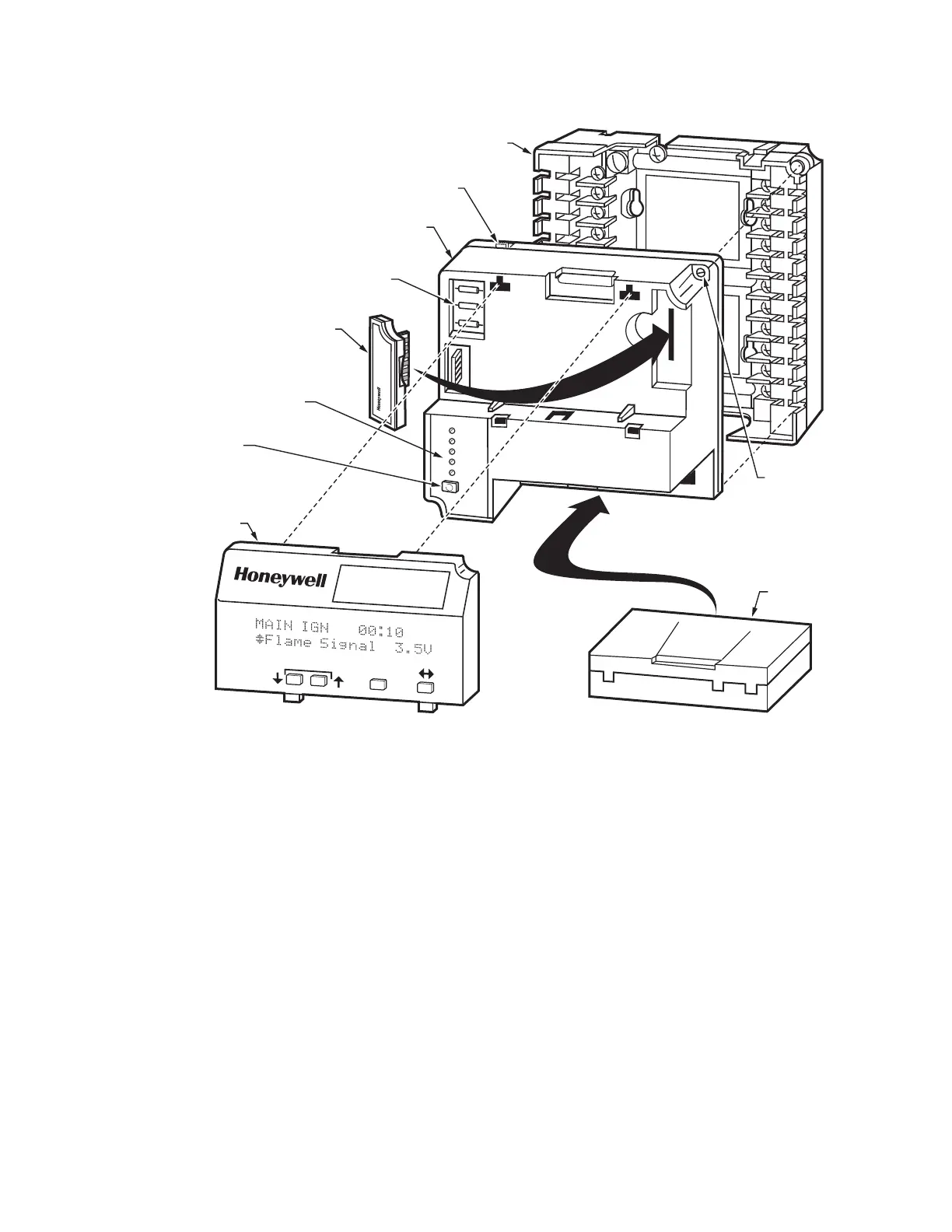
Fig. 25. Sequence Status LEDs.
SETTINGS AND
ADJUSTMENTS
Selectable Site-Configurable
Jumpers
The relay module has three site-configurable jumper
options, see Fig. 25 and Table 8 on page 20. If necessary,
clip the site-configurable jumpers with side cutters and
remove the resistors from the relay module.
SERVICE NOTE: Clipping and removing a site-
configurable jumper enhances the level of safety.
IMPORTANT
Clipping and removing a jumper after 200 hours of
operation causes a nonresettable Fault 110. The
relay module must then be replaced.
HONEYWELL
POWER
PILOT
F
LAME
MAIN
ALARM
RESET
OPTIONAL
KEYBOARD
DISPLAY
MODULE
(STANDARD ON
RM7800G,L)
PURGE
TIMER
Q7800A1005
(plastic panel
mount version)
CAPTIVE
MOUNTING
SCREW
RUN/TEST
SWITCH
CONFIGURATION
JUMPERS
RELAY
MODULE
SEQUENCE
STATUS
LED PANEL
RESET
BUTTON
FLAME
AMPLIFIER
SCROLL
MODE
- S
AV
E -
BURNER CONTROL
M23166
 Loading...
