RM7898A 7800 SERIES VALVE PROVING PRIMARY RELAY MODULES
32-00209-03 20
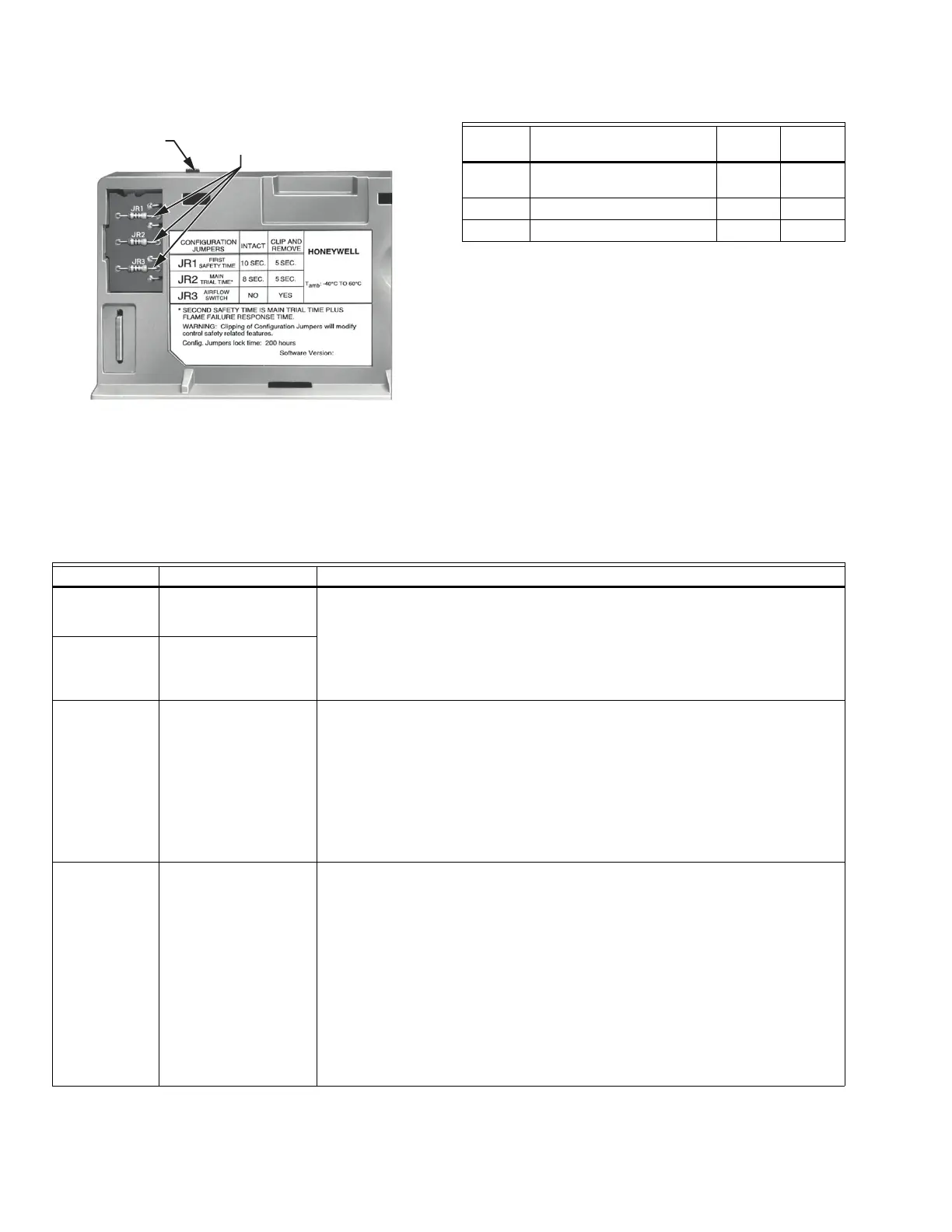
Fig. 26. Selectable site-configurable jumpers.
Table 8. Site-configurable jumper options.
TROUBLESHOOTING
The POWER LED provides fault identification when the
Relay Module locks out on an alarm. Fault identification is
a series of fast- and slow-blinking LED lights. The fast
blinks identify the tens portion of the code (three fast
blinks is 30), while the slow blinks identify the units
portion of the code (two slow blinks is 2). Three fast blinks
followed by two slow blinks would be code 32. This
identifies a running interlock on during STANDBY. (See
Table 9 for Blink Fault Code List.)
The LED code repeats as long as the fault exists. To clear
the fault, press the RESET button.
SELECTABLE
CONFIGURATION JUMPERS
RUN/TEST
SWITCH
M7701C
Jumper
Number Description Intact Clipped
JR1 Pilot Flame Establishing
Period (PFEP)
10
seconds
4
seconds
JR2 Flame Fail Recycle Lockout
JR3 Interlock Recycle Lockout
Table 9. Blinking Fault Codes and Recommended Troubleshooting.
Blink Code System Failure Recommended Troubleshooting
Code 1-1
*Low AC Line
Voltage*
Low AC Line detected. 1. Check the Relay Module and Display Module connections.
2. Reset and sequence the Relay Module.
3. Check the 7800 power supply and make sure that frequency and voltage
meet specifications.
4. Check the backup power supply, as appropriate.
Code 1-2
*AC Quality
Problem*
Excessive noise or
device running on
slow, fast, or AC line
dropout detected.
Code 2-1
*Unexpected
Flame Signal*
Flame sensed when no
flame is expected
during STANDBY or
PURGE.
1. Check that flame is not present in the combustion chamber; correct any
errors.
2. Make sure that the flame amplifier and flame detector are compatible.
3. Check the wiring and correct any errors.
4. Remove the flame amplifier and inspect its connections. Reseat the
amplifier.
5. Reset and sequence the Relay Module.
6. If the code reappears, replace the flame amplifier and/or the flame detec-
tor.
7. If the fault persists, replace the Relay Module.
Code 2-2
*Flame Signal
Absent*
No-flame time present
at the end of the PIlot
Flame Establishing
Period; lost during the
Main Flame
Establishing Period or
during RUN.
1. Measure the flame signal. If one exists, verify that it meets specifications.
2. Make sure that the flame amplifier and flame detector are compatible.
3. Inspect the main fuel valve(s) and valve connection(s).
4. Verify that the fuel pressure is sufficient to supply fuel to the combustion
chamber. Inspect the connections to the fuel pressure switches. Make
sure they are functioning properly.
5. Inspect the Airflow Switch and make sure that it is functioning properly.
6. Check the flame detector sighting position; reset and recycle. Measure the
flame signal strength. Verify that it meets specifications. If not, refer to the
flame detector and/or flame amplifier checkout procedures in the instal-
lation instructions.
7. Replace the flame amplifier and/or the flame detector, if necessary.
8. If the fault persists, replace the Relay Module.
 Loading...
