RM7898A 7800 SERIES VALVE PROVING PRIMARY RELAY MODULES
25 32-00209—03
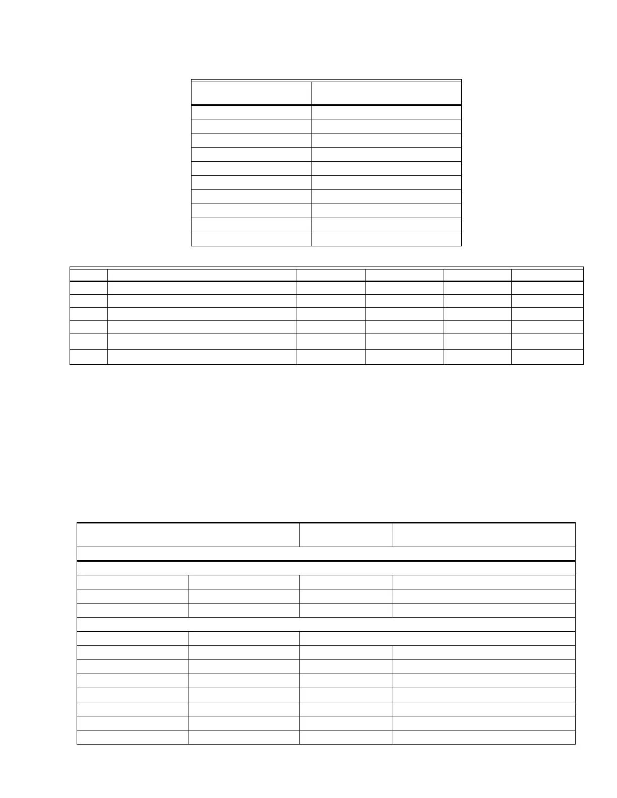
Table 14. Schedule 40 Pipe Internal Cross-Sectional Area.
Table 15. VPS Worksheet.
a
Divide inches w.c. by 27.7 to get psi.
b
Divide Btuh by 1000 to get cf/hr for natural gas or by 2550 to get cf/hr for LP gas.
APPENDIX B - IGNITION
OPTIONS
Column 1 lists the ignition options.
Column 2 lists the drawing that provides that option. The letter refers to drawings on pages 24–28.
Column 3 refers to the number of poles required on the Fuel Changeover Switch.
Pipe Size NPT (Inches)
Cross-Sectional Area (Sq. In.)
“A”
3/8 0.191
1/2 0.304
3/4 0.533
1 0.864
1-1/4 1.498
1-1/2 2.036
2 3.356
2-1/2 4.788
3 7.393
4 12.730
Item Description Information Lookup Table Results Formula Item
V1 Upstream Valve Volume 12 V1
V2 Downstream Valve Volume 13 V2
D Pipe Size NPT (in.) 14 A
LPipe Length (ft) — L
P
Valve Inlet Pressure (psig)
a
—P
C
Burner Maximum Firing (cf/hr)
b
—C
Table 16. Ignition options.
IGNITION OPTIONS
DRAWING I.D.
CODE
FUEL CHANGEOVER POLES
REQUIRED
NO VALVE PROVING
Single Fuel
Interrupted Pilot A - -
Intermittent Pilot B - -
Direct Spark Ignition C - -
Dual Fuel
Gas Oil
10 sec. Interrupted Pilot 10 sec. Interrupted Pilot D 2
10 sec. Interrupted Pilot Intermittent Pilot E 3
10 sec. Interrupted Pilot Direct Spark Ignition F 3
Intermittent Pilot 10 sec. Interrupted Pilot G 3
Intermittent Pilot Intermittent Pilot H 2
Intermittent Pilot Direct Spark Ignition I 4
Direct Spark Ignition 10 sec. Interrupted Pilot J 3
 Loading...
