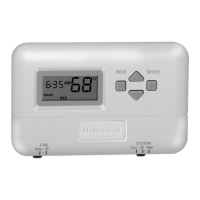
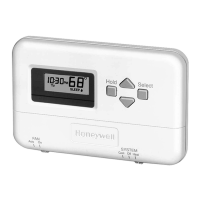
T8002 PROGRAMMABLE THERMOSTAT
YES
1
5 FEET
[15 METERS]
!
J
J
J
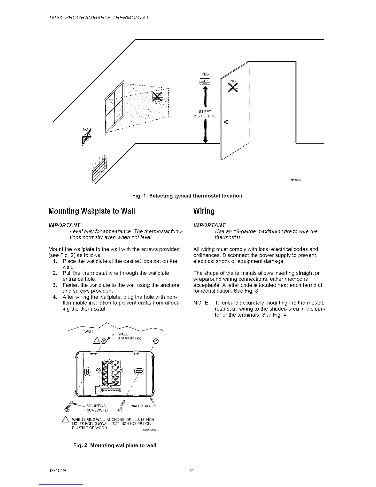
Fig. 1. Selecting typical thermostat location.
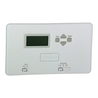
MountingWallplate to Wall
IMPORTANT
Level only for appearance. The thermostat func-
tions normally even when not level.
Mount the walplate to the wall with the screws provided
(see Pig. 2) as folows:
1. Place the wa/plate at the desired location on the
wal.
2. Pull the thermostat wire through the wallptate
entrance hole.
3. Fasten the walplate to the wall using the anchors
and screws provided.
4. After wiring the wallplate, plug the hole with non-
flammable insulation to prevent drafts from affect-
ing the thermostat.
AJ A%,%°Rs®
/ /
j WALL'S=E\
WHEN USING WALL ANCHORS, DRILL 3/16 INCH
HOLES FOR DRYWALL, 7/32 INCH HOLES FOR
PLASTER OR WOOD
M12202A
Wiring
IMPORTANT
Use an f8-gauge maximum wire to wire the
thermostat
All wiring must comply with local electrical codes and
ordinances. Disconnect the power supply to prevent
electrical shock or equipment damage.
The shape of the terminals allows inserting straight or
wraparound wiring connections; either method is
acceptable. A letter code is located near each terminal
for identification. See Fig. 3.
NOTE: To ensure accurately mounting the thermostat,
restrict all wiring to the shaded area in the cen-
ter of the terminals. See Fig. 4.
Fig. 2. Mounting wallplate to wail.
69-1549 2
 Loading...