GB
Honeywell GmbH 6 MU0H-2327GE23 R0618
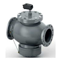
2.1.7Removal
If the actuator has to be removed, follow the next procedure:
1. Turn the connection ring between valve and actuator
2. Remove the actuator
3 External Interface
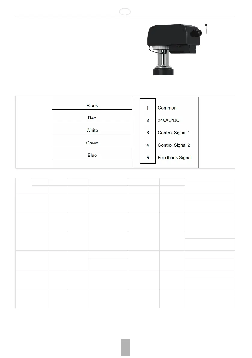
3.1 Wires indication
3.2 Actuator Wiring Guide
• and are power cables
• and are signal cables
• is the exclusive feedback cable
Input
Number 1 2 3 4 5
Remarks
Colour Black Red White Green Blue
Internal control Common 24 AC/DC
Feedback:
0(2) - 10 V
0(4) - 20 mA
Power: cable 1 - 2
Voltage signal Common 24 AC/DC
0 - 10 V DC
2 - 10 V DC
Feedback:
0(2) - 10 V
0(4) - 20 mA
Power: cable 1 - 2
Voltage signal: cable 1 - 3
Current signal Common 24 AC/DC
0 - 20 mA
4 - 20 mA
Feedback:
0(2) - 10 V
0(4) - 20 mA
Power: cable 1 - 2
Current signal: cable 1 - 3
ON/OFF signal Common 24 AC/DC
24 V DC (open) Feedback:
0(2) - 10 V
0(4) - 20 mA
Power: cable 1 - 2
0 V (close)
ON/OFF signal: cable 1 - 3
3 points floating Common 24 AC/DC Opening 24 V AC/DC
Closing 24
V AC/DC
Feedback:
0(2) - 10 V
0(4) - 20 mA
Power: cable 1 - 2
Floating 3 points: cable 3 - 4
PWM control Common 24 AC/DC PWM signal
Feedback:
0(2) - 10 V
0(4) - 20 mA
Power: cable 1 - 2
PWM control: cable 1 - 3
 Loading...