GB
MU0H-2327GE23 R0618 7 Honeywell GmbH
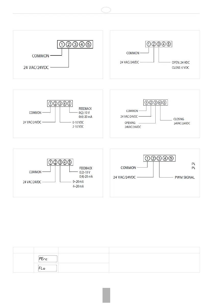
4 Control Method
1. Internal control*
2. Voltage signal
3. Current signal
4. ON/OFF
5. 3 points signal
6. PWM signal
* Flow rate can be set by buttons on the actuator and read on the 4 digits display.
5 Initial Setting
Power on display indicates ’Go-0’ and automatically adjusts the initial setting to the valve zero point.
Do not press any buttons as this might wrongly adjust the initial setting of the valve zero point; this may cause incorrect flow
control.
The actuator has a built in safety function which can be activated when the zero point cannot be set automatically.
It is activated with the Down button and stops the "Go-0" process.
The zero point may be forced by using the Down button.
How to set: Press the Mode button (about 2 seconds) to switch to the setting mode.
PWM Type 1: 0.1 - 5 s/Step 20ms
PWM Type 2: 0.1 - 25 s/Step 100ms
Indication Meaning Operating
SET1 Input internal control in % Select with up/down buttons and then press “MODE“ to
confirm
Input internal control in flow rate
 Loading...