Installation Instruction VARIODYN
®
D1 System
FB 798663.GB0 / 05.19 19
DOM
DOM
PA1
PA2
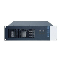
Example
total weight ca. 40 kg
drawer rail or
installation bracket
below the amplifier
PA1 = 2 x 200 W
PA2 = 2 x 200 W
Fig. 8: Example installation of devices with installation bracket (Example)
Device Weight Device Weight
Amplifier 2XH250 / 2XH500
Digital-Output-Module (DOM 4-8)
Amplifier 2XD250 / 2XD400 approx. 19 Kg Digital-Output-Module (DOM 4-24) approx. 6,5 Kg
Amplifier 4XD und 4XV-Serie
View-Control-Module (VCM)
Universal-Interface-Module (UIM)
System-Communication-Unit (SCU) approx. 3 Kg
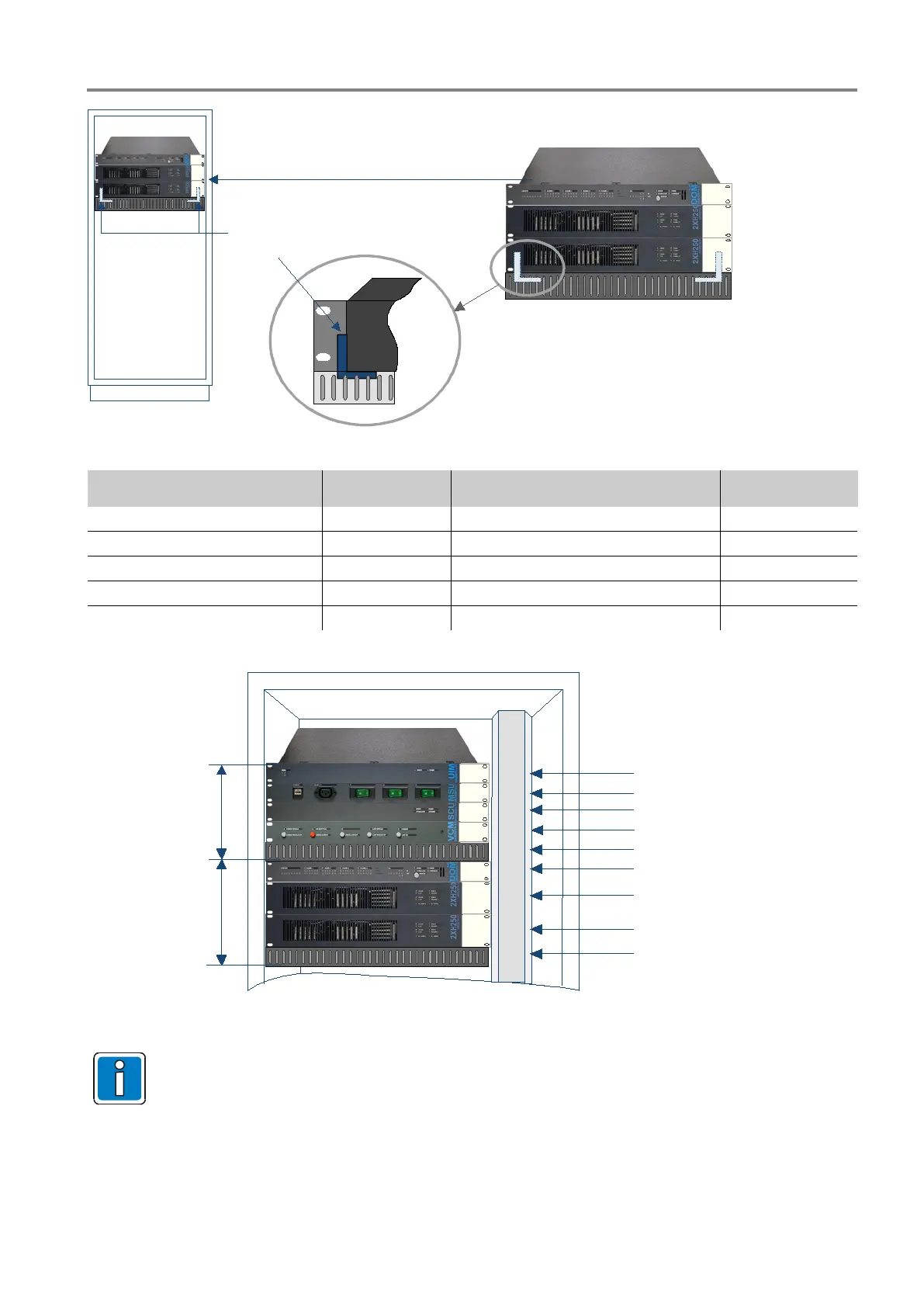
Ventilation field
Ventilation field
6HU
5HU
DOM
PA1
PA2
UIM
SCU
MSU
VCM
Fig. 9: Sample arrangement of the devices
•
As a rule, in a cabinet, the heavy devices should be installed on the bottom and the lighter
components should be installed towards the top. Two power amplifiers installed on top of each other
must be additionally fastened with suitable installation brackets.
• If components are included in addition to the MSU (SCU, UIM, VCM
), they should also be installed
with a ventilation field below them and fastened with corresponding installation brackets.
 Loading...
