Installation Instruction VARIODYN
®
D1 System
FB 798663.GB0 / 05.19 21
Wiring of the loudspeaker
5.1.1 Spur
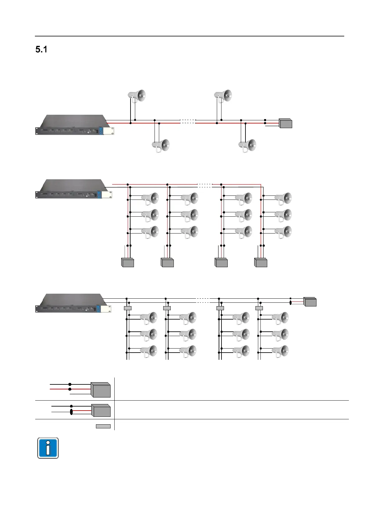
The End of line module (EOL-Part No. 583496) for terminating the loudspeaker circuits for standardised system
monitoring if more than 20 loudspeakers are connected per line. The EOL is connected at the end of the line, after
the last loudspeaker.
Fig. 10: Wiring with more than 20 loudspeaker
DOM
EOL EOL EOL EOL
black
red
white
black
red
white
black
red
white
black
red
white
Fig. 11: Wiring of loudspeaker as monitoring spur line incl. EOL
Fig. 12: Wiring of loudspeaker incl. EOL and volume controller
Up to 250 W (inclusive)
As of 250 W or with volume controller
Volume controller (Part No. 581321, 581322, 581323)
•
The loudspeakers can be connected using communications cable I-Y (St) Y n x 2 x 0.8 mm or
comparable
, for example. If a different, comparable cable type is used, please bear in mind the
output and cable length required.
• Spur lines with volume controllers are not monitored!
• To ensure correct loudspeaker monitoring by means of impedance measurement, a maximum of
20 loudspeakers are permitted per line. If more than 20 loudspeakers are used, an End of Line
module (EOL) must be connected.
 Loading...
