Installation Instruction VARIODYN
®
D1 System
FB 798663.GB0 / 05.19 61
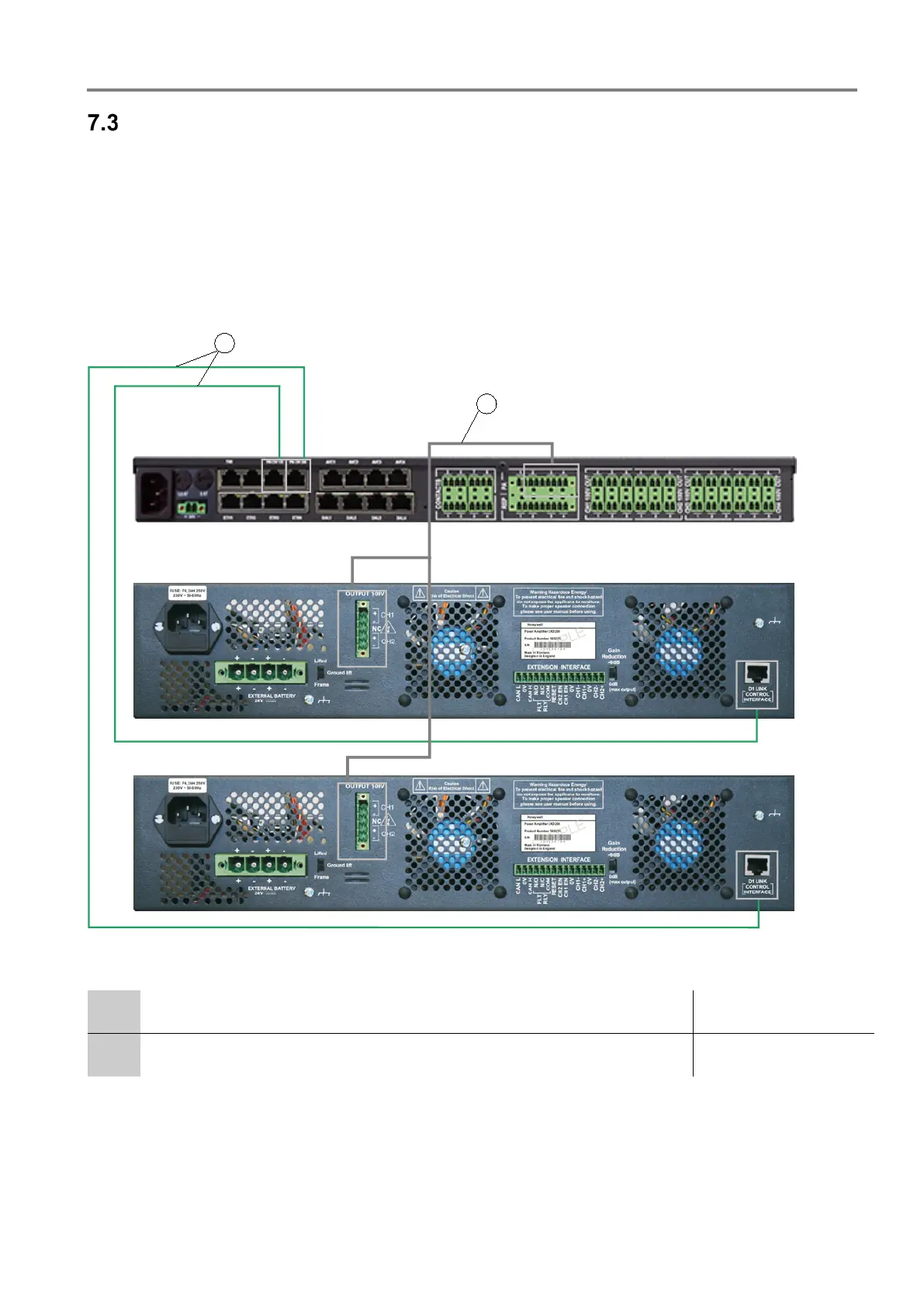
Connect - 2XH and 2XD-series
1. Connect the power amplifier to the switched power supply of the MSU. If an MSU is not present, connect the
power amplifier directly to the power supply / emergency power supply.
2. Use the prefabricated cable (Part. No. 583477.21) to connect the PA output of the DOM and the D1 LINK
CONTROL INTERFACE socket of the power amplifier.
3. Use the input cable DOM amplifier (Part No. 583491A) to connect the SPK-OUTPUT on the power amplifier
and PA input of the DOM – be sure to use the correct socket!
4. The amplifier must be connected to a programmed DOM for correct operation.
5. Connect additional power amplifiers accordingly.
Fig. 53: Connection of the inputs/outputs
Input cable DOM amplifier AF output signal to power amplifier (PA)
Part No. 583491A
*5
Output cable 2 amplifier - DOM Part No. 583477.21
*5
*5
Depending on the hardware version of the DOM and the power amplifiers, the system cables (Part No. 583471.21 and 583476.21) may
also be used. If the DOM and power amplifier hardware versions differ, the system cables (Part No. 583472.21 and 583473.21) should be
used.
 Loading...
