Installation Instruction VARIODYN
®
D1 System
70 FB 798663.GB0 / 05.19
Connect - 4XD and 4XV-series
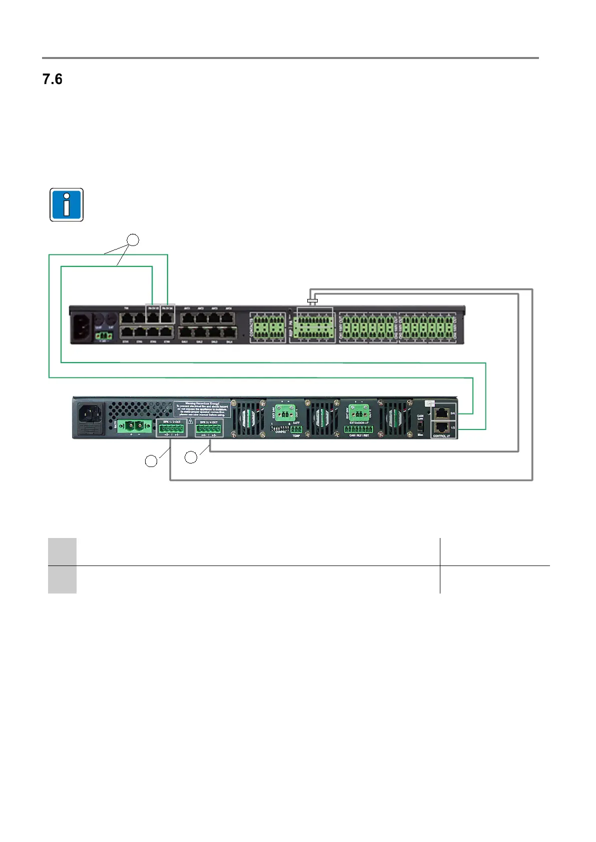
7.6.1 Connection DOM and Power Amplifier
1. Connect the DOM with the redundant power supply of the power amplifier.
2. Connect the PA output of the control unit and the D1 LINK CONTROL INTERFACE socket of the power
amplifier with the green input cable DOM-Amplifier (Part No. 583491A).
3. Connect the SPK OUTPUT on the power amplifier and the IN PA input of the DOM using the amplifier - DOM
grey output cable (Part. No. 583477.21) – ensure that the correct slot is used as per the cable labelling.
Connect channels CH1/2 (left slot) and CH 3/4 (right slot) on the power amplifier 4XD125B as per the
figure below.
Fig. 64: Connection of the inputs/outputs (example with 4XD125B)
Input cable DOM amplifier (0,5 m, green) AF output signal to power amplifier (PA)
Part No. 583491A
Output cable 2 amplifier - DOM Part No. 583477.21
 Loading...
