XNX Universal Transmitter Quick Start Guide
10
WARNING
When the XNX is equipped with the optional Remote Mount Kit, the remote sensor MUST be securely
mounted to a xed position. The Remote Sensor Kit is not intended to be used as a hand-held
detector.
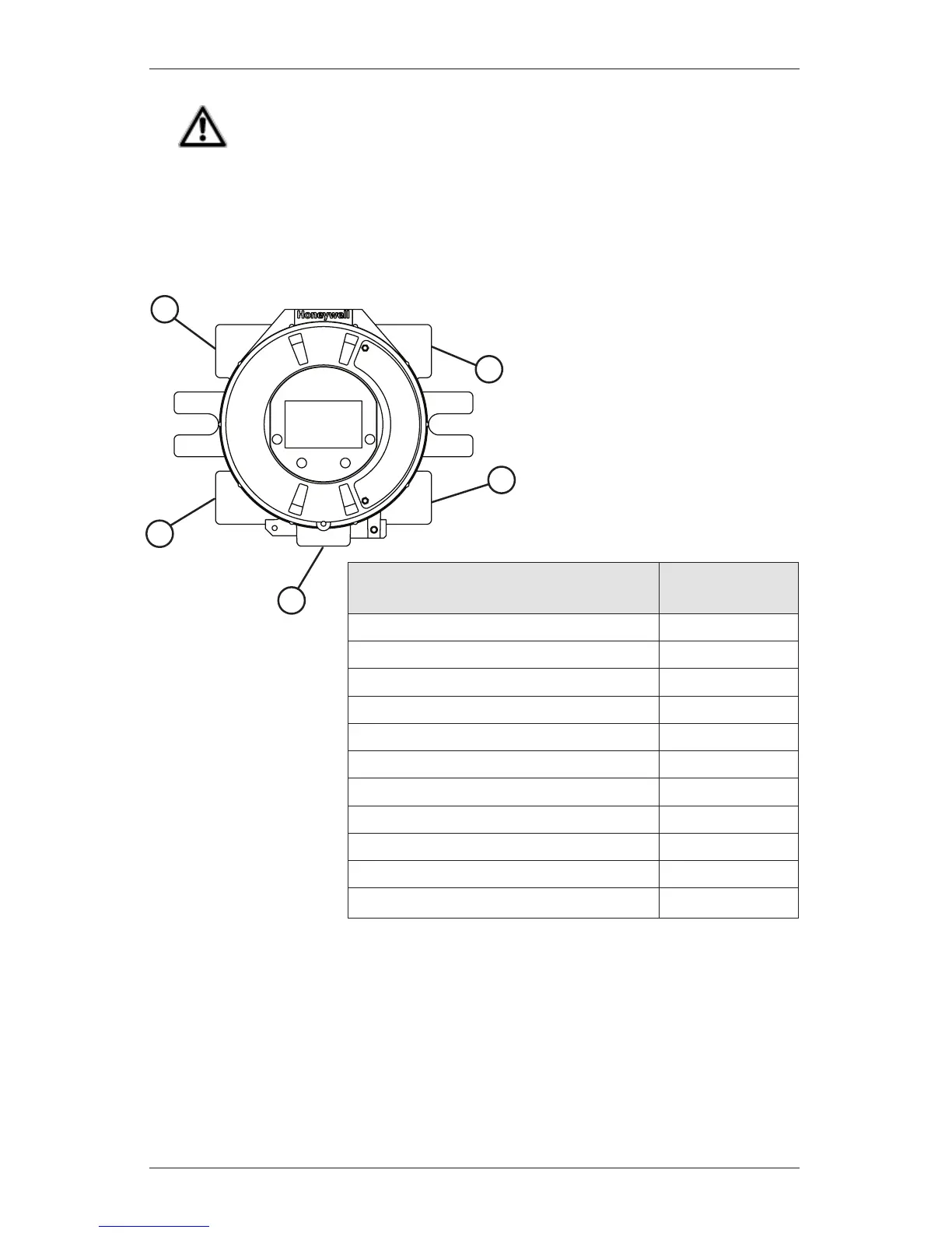
The XNX is configured with 5 cable/conduit entries built into the housing
for wiring and mounting sensors. Figure 3 provides the guidelines to proper
installation of the XNX.
NOTE
While relay wiring can use
any available cable/conduit
entry in the XNX enclosure,
do not use the same cable/
conduit entry for both relay
reset and relay signal lines to
avoid electrical noise.
Option Position
Local HART
®
Option B
MPD, 705 Series, Sensepoint Series C
Catalytic Bead Sensor C
Searchpoint Optima Plus A or E
Searchline Excel Typically C
Remote Sensor Connection (except EC ) Any remaining
Searchpoint Optima Plus - Remote Any remaining
Modbus
®
Any remaining
Relays Any remaining
Foundation Fieldbus Any remaining
Power Any remaining
A
E
D
B
C
*
* Limited access due to
IS barrier if equipped with
electrochemical cell.
Figure 3. XNX Universal Transmitter cable/conduit entry assignments
 Loading...


