XNX Universal Transmitter Quick Start Guide
25
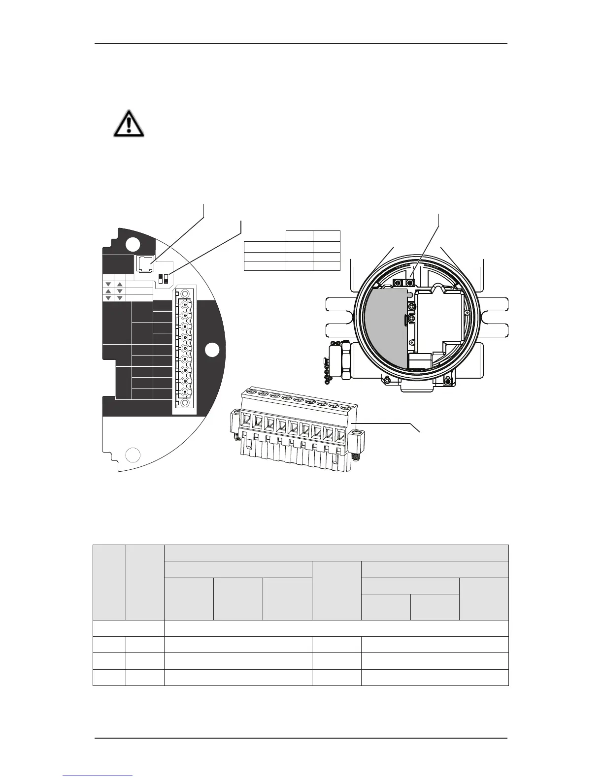
NOTE
The black and red wires f.rom the MPD are not used with the XNX
mV Personality Board. Ensure that they are properly isolated from live
connections. DO NOT CUT.
CAUTION
Be certain to dress the wires properly to ensure cabling does not contact switches 1-2 on the back
of the POD. Do not force the POD into the enclosure as it may indicate an interference condition
resulting in damage to the wiring, POD or switch settings.
HART
20 mA
Operation
LOCAL
J1
S1
+V 1-1
mV TB-1
MPD, 705
Sensepoint
4-20mA
HART
16-32 VDC
6.5W max.
1-2
-V 1-3
1-4
+mA 1-5
-mA 1-6
Sense
1-7
0v 1-8
Ref 1-9
S1
Source
Sink
Isolated
S2
S2
J1 - Local HART Option Connector
1
2
3
4
5
6
7
8
9
internal
grounding lugs
S1 and S2 - 20mA Output
Jumper Switch
S2
S1
▼
▼
Isolated
▲
Sink
▼
Source
▼
▲
XNX mV TB-1
Figure 13. XNX mV personality board wiring
TB-1 Desc�
Wire Color from Sensor
mV Catalytic Bead Sensor
Sensept
PPM*
mv MPD w/IR Sensor
MPD
705
705HT
Sensept
Senspt
HT
IR 5%
IR Flam
CO
2
CH
4
Pins 1-6 See subsections in Section 4.4 for pin identication
7 Sense Brown Red Brown
8 0v White Green White
9 Ref Blue Blue Blue
*Internal earth ground; approximately one inch of the black sheath that contains the Sensepoint PPM’s
four wires (red, blue, green, silver) must be split to allow the silver grounding wire to reach the internal
grounding lugs.
 Loading...


