2-20
Installing the Switch
Sample Network Topologies
As shown in the above illustration, the IP telephones can be connected in line,
that is, between the switch and the end device, in this case a PC. The IP
telephones have two ports, one in and one out. Therefore the phone receives
voice and power from the switch and the PC can send and receive data through
the phone to the switch.
The end node devices are connected to the switch by straight-through or
crossover twisted-pair cables. Either cable type can be used because of the
Auto-MDIX feature on these Switches.
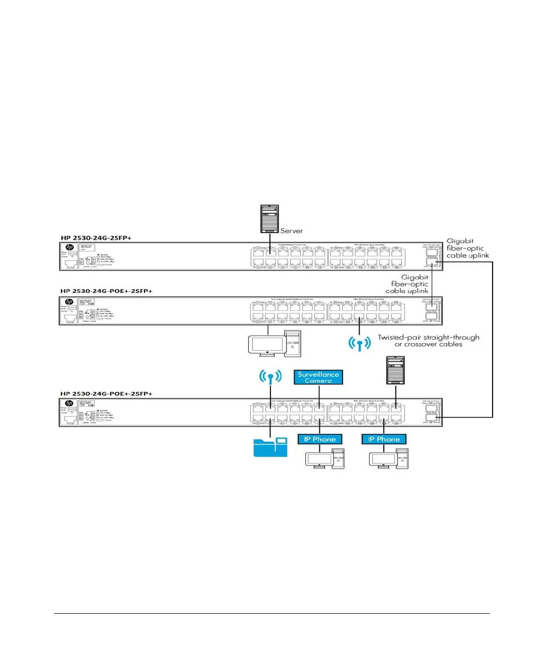
As a Segment Switch Implementing PoE
Figure 2-11. Segment network configuration with PoE switches
These Switches also work well as segment switches. That is, with their high
performance, they can be used for interconnecting network segments—
simply connect the network devices that form those segments to the Switches.
In the illustration above, 2530-24G-PoE+-2SFP+ Switches with PCs, printers,
and local servers attached, are both connected to a non-PoE switch. The
devices attached to the two 2530-24G-PoE+-2SFP+ Switches can now

 Loading...