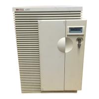
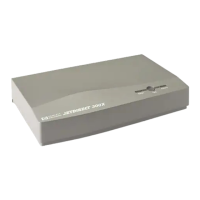
Peripheral Equipment
Be sure to refer to the documentation that comeswith any peripheral equipment for specific
installation instructions.
DTC Installation
There may be multiple DTCs to be installed on the system. Repeat the installation
instructions for each DTC installed on the system.
1. The DTC
is
connected to the SPU through the LAN link.
2. Connect another BNC T connector (part number 92227N)to the connectorlabeled
LAN
Interface
on the back of the DTC.
3. Connect the LAN cable (all ready connected to the SPU) to the DTC BNC T connector.
4. If there is another DTC, connect a LAN cable from the other end of the BNC T connector
to the next DTC.
5. On the last DTC installed, connect a LAN terminator (part number 92227P) to the
remaining side of the BNC T connector assembly.
6. Cover all the BNC T connector assemblieswith the fabric anti-static coverthat came with
the T connector.
7. Refer to the documentation that came with the DTC for complete installation and
configuration instructions.
Note
Be sure that each end of the system LAN link has a BNC LAN Terminator
(part number 92227P) installed.
PowerTrust UPS
To connect the PowerTrust UPS to the SPU, perform the followingsteps:
1. Locate the PowerTrust System Guide (part number 5961-8383).
2. Take the time to thoroughly read and understand all the necessary procedures outlined in
the PowerTrust Guide. The PowerTrust requires recharge time beforeit is considered ready
for normal operation.
Note
"
The line cord for the computer is used as the line cord for the UPS. The
computer
is
connected to the UPS with a conveniencecord supplied with the
UPS. Be sure the appropriate localized line cord is used with the UPS (refer
to Table 4-1).
4-4 Installation
 Loading...
