Model 333A/334A
Section
IV
becomes abnormally large
during
anoverload,
A2CR8
breaks down and provides
a
lower resistance charg-
ing
path
for A2C15, which reduces the transient re-
covery time
of
the meter amplifier.
Negative ac feed-
back
is
applied from the collector circuit of
A2Q9
to
the emitter circuit
of
A2Q5.
This feedback
is
used
to
ensure
flat
frequency response, to improve
linear-
ity,
and
to reduce the effect
of
variationof transistor
parameters with environmental changes.
In
this
manner, the calibration
of
the instrument
is
made
dependent on high quality passive components.
4-47. METER RECTIFIER CIRCUIT.
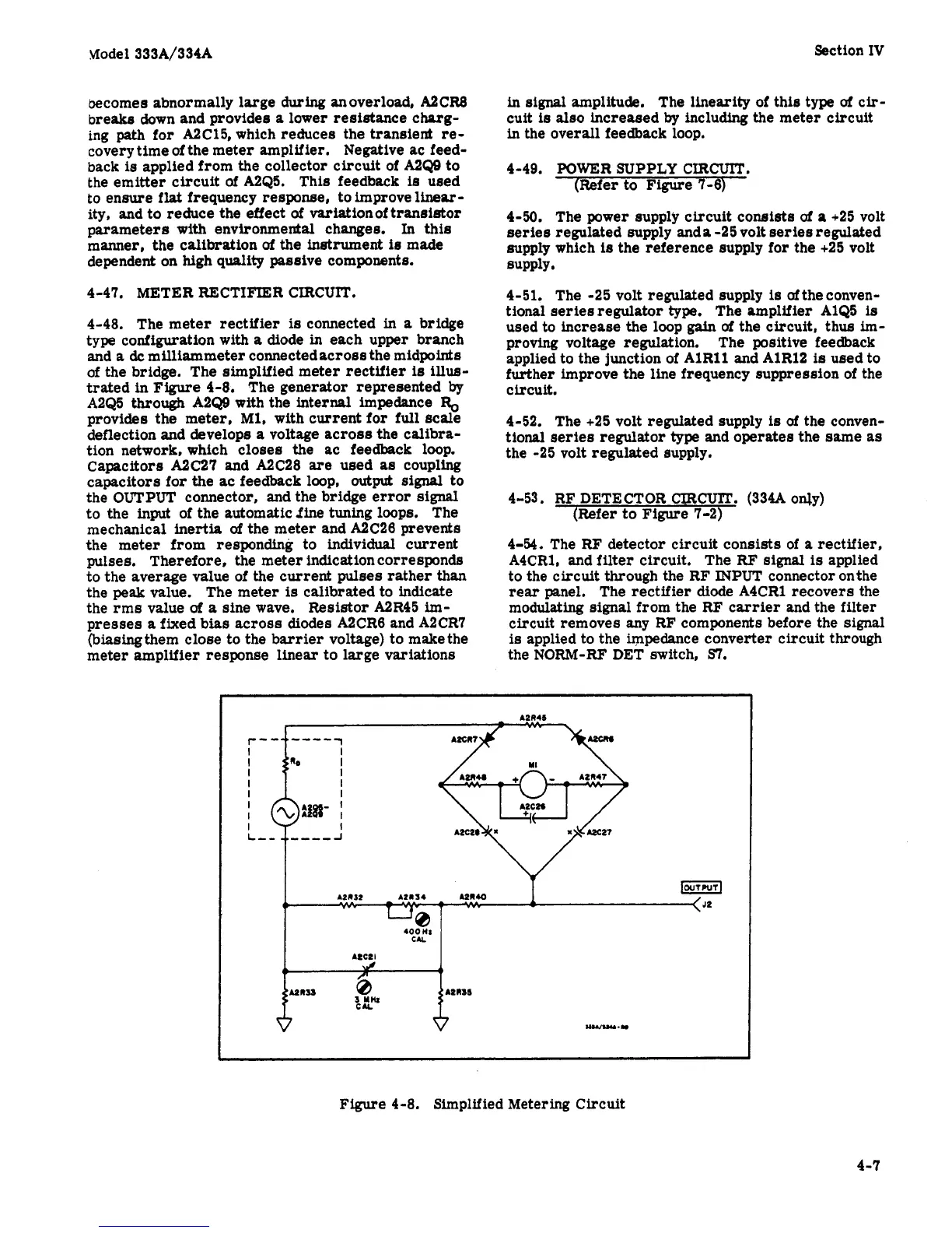
4-48. The meter rectifier
is
connected in
a
bridge
type configuration with
a
diode in each upper branch
and
a
dc
milliammeter connectedacross the midpoints
of
the bridge. The simplified meter rectifier
is
illus-
trated
in
Figure
4-8. The generator represented
by
A2Q5
through
A2Q9 with the internal impedance
%
provides the meter,
Ml,
with current for
full
scale
deflection and develops
a
voltage across the calibra-
tion network, which closes the ac feedback loop.
Capacitors
A2C27
and A2C28 are used
as
coupling
capacitors for the ac feedback loop,
outw
signal
to
the
OUTPUT
connector, and the bridge error
signal
to the
input
of the automatic
fine
tuning loops. The
mechanical inertia
of
the meter and A2C26 prevents
the meter from responding to individual current
pulses, Therefore, the meter indication corresponds
to
the
average value of the current pulses rather than
the
peak
value. The meter
is
calibrated to indicate
the rms value
uf
a
sine wave.
Resistor
A2R45 im-
presses
a
fixed
bias
across diodes A2CR6 and A2CR7
(biasingthem close to the barrier voltage) to makethe
meter amplifier response linear to large variations
in
signal
amplitude. The linearity of this type
uf
cir-
cuit
is
also increased
by
including the meter circuit
in the overall feedback loop.
4-49. POWER
SUPPLY
CIRCUIT.
(Refer to Figure
7-6)
4-50. The power supply circuit consists
of
a
+25 volt
series regulated supply anda -25 volt series regulated
supply which
is
the reference supply for the +25 volt
SUPPlY
4-51. The -25 volt regulated supply
is
oftheconven-
tional aeriesregulator
type.
The amplifier A1Q5
is
used to increase the loop
gain
of
the circuit,
thus
im-
proving voltage regulation. The positive feedback
applied to the junction of AlR11 and AlR12
is
used to
further
improve the line frequency suppression of the
circuit.
4-52. The +25 volt regulated supply
is
of
the conven-
tional
series
regulator
type
and operates the same
as
the -25 volt regulated supply.
4-53. RF DETECTOR
CIRCW".
(334A
only)
(Refer
to Figure 7-2)
4-54. The
RF
detector circuit consists of
a
rectifier,
A4CR1,
and
filter
circuit. The
RF
signal
is
applied
to the circuit through the RF
INPUT
connector onthe
rear panel, The rectifier
diode
A4CR1 recovers the
modulating signal from the RF carrier and the filter
circuit removes
any RF components before the
signal
ia applied to the impedance converter circuit through
the NORM-RF DET switch.
SI.
Figure 4-8. Simplified Metering Circuit
r-
I
I
I
I
I
I
I
I
L-
4-7
 Loading...


